Radiation Protection in the Operating Room
Objectives:
- Recognize the different radiologic equipment used in the OR
- Define and explain the radiation measurements
- Determine the recommended radiation dose thresholds
- Distinguish the biological effects and risks associated with radiation exposure
- Employ the correct radiation protection techniques in the OR
- List the various personal radiation measurement devices
- Identify and properly use the radiation protection apparel and barriers in the OR
Description:
This article covers the radiation protection techniques that are currently used in the Operating Room when ionizing radiation is needed. It highlights the radiation measurements, the occupational exposure guidelines, as well as the dangers and risks related to radiation exposure. It explains the core concepts of radiation protection and describes the personal radiation measurement devices and protective apparel that should be available and properly used by the concerned Operating Room staff. This article is accredited by the ASRT for 1.5 Category A CE Credits.
In this course we will mainly learn about the best Radiation Protection best practices in the Operating Room. However, before we get deep into the topic, we will first introduce the ionizing radiation concept, the ALARA principle, and the concept of radiation hormesis. Then we will tackle the commonly used terminology and describe the various interactions of x-ray and matter. And finally, we will discuss the implication of medical imaging in the Operating Room and the optimal measures to implement in the operating room from radiation exposure point of view.
Radiography is an important tool in nondestructive evaluation. The method offers a number of advantages over other NDE methods, but one of its disadvantages is the health risk associated with the radiation. Health effects can occur due to either long-term low level exposure or short-term high level exposure. There is a long story behind the development of radiodiagnosis from X-rays to the Current CT scans.
X-rays were discovered in 1895 by Wilhelm Conrad Roentgen (1845-1923) who was a Professor at Wurzburg University in Germany. Working with a cathode-ray tube in his laboratory, Roentgen observed a fluorescent glow of crystals on a table near his tube.
Shortly after the discovery of x-rays, another form of penetrating rays was discovered. In 1896, French scientist Henri Becquerel discovered natural radioactivity. He discovered this phenomenon while investigating the properties of fluorescent minerals.
While working in France at the time of Becquerel’s discovery, Polish scientist Marie Curie discovered radium. By 1929, industrial radiation sources were becoming available for radiographing extremely thick materials. Exposure times were long, and often radiographers were exposed to excessive doses of radiation.
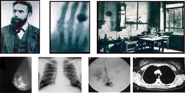
Before we begin to talk about radiation protection need and responsibilities, let’s start by defining the ionizing radiation.
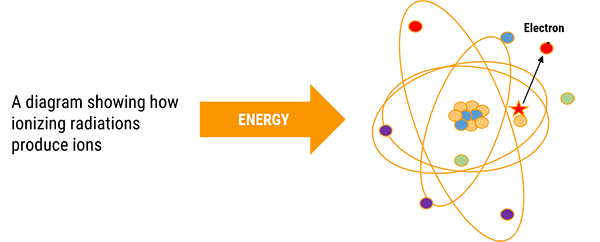
Ionizing radiation is any type of particle or electromagnetic wave that carries enough energy to ionize or remove electrons from an atom. The transfer of kinetic energy from one location to another is called radiation.
When they pass through matter, x-rays produce electrically charged particles. Because of these ions, the process is termed ionizing radiation. The production of these ions as well as the electrons ejected in the process may cause injury to biological tissue. There are various consequences to this process.
Ionizing Radiation
| Definition | Sources |
|
|
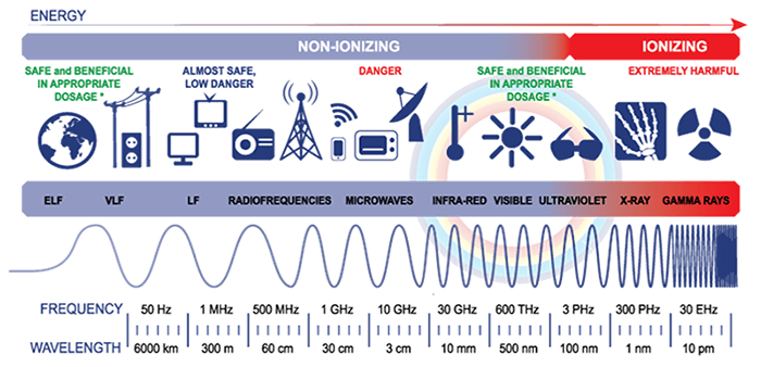
Radiation is kinetic energy and exists in many forms. The full range of frequencies and wavelengths of electromagnetic waves is known as the electromagnetic spectrum.
Frequency is given in hertz (Hz), wavelength is given in meters, and energy is given in electron volts (eV). A unit of energy is equal to the quantity of kinetic energy an electron acquires as it moves through the potential difference of 1 volt. All forms have one common characteristic which is their velocity that is equal to the speed of light.
Gamma, X, and ultraviolet light with energies greater than 10 eV are considered to be ionizing radiation as they have sufficient kinetic energy to eject electrons from the atom.
Ultraviolet with energies less that 10 eV, visible light, infrared rays, microwaves, and radiowaves do not have the sufficient kinetic energy, therefore they are considered to be non-ionizing radiation.
Need for Radiation Protection
Since ionizing radiation is harmful, the American Association of Radiologic Technologists (ASRT) and the Joint Commission (TJC) encourage health care providers to establish a culture of quality, patient safety, and high reliability while working as a team.
Radiologic technologists and radiologists are educated in safe operation of all imaging equipment, use protective devices whenever possible, follow established procedures, and establish machine settings to reduce radiation exposure thus reducing the possibility of causing damage to healthy biological tissue. This protects persons from both short and long term effects of radiation. Some occur in just specific organs and organ systems while others such as cancer and hereditary effects, affect the whole body and future generations.
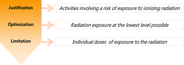
Justification of Radiographic Procedures
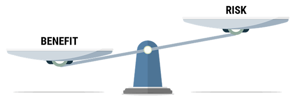
The realized benefits of radiation exposure should far outweigh any slight chance of inducing a radiogenic malignancy or any genetic defects. Thus, all occupational workers have the responsibility to keep radiation doses to the minimum: Ordering physicians, radiologists and technologists.
Diagnostic efficacy is the degree to which a diagnostic study accurately reveals the presence of disease in the patient while adhering to radiation safety guidelines.
Radiation Protection Responsibilities
The ordering physician and the radiologist have the acceptance of responsibility for keeping orders for procedures involving ionizing radiation to the minimum and referring patients to qualified professionals.
Justification means that a practice that entails or that could entail exposure to radiation should only be adopted if it yields sufficient benefit to the exposed individuals, or to society to outweigh the radiation detriment it triggers.
Individual doses due to the combination of exposures from all relevant practices should not exceed specified dose limits.
Radiation sources and installations should be provided with the best available protection and safety measures under the prevailing circumstances, so that the magnitudes and likelihood of exposures and the numbers of individuals exposed be as low as reasonably achievable. Economic and social factors being taken into account, and the doses they deliver and the risk they entail be constrained.
A thorough patient history and proper patient screening is essential, including but not limited to LMP for female patients, as well as radiation exposure history and the patient’s chief complaint. Accuracy of patient positioning and selecting the appropriate technique for the procedure will ensure the production of optimal images the first time.
Collimation and shielding of the patient will reduce radiation exposure to the patient, and the radiologic technologist should always maintain the personal protective equipment (PPE) in good condition.
Effectively what really matters is to protect the individual, prevent deterministic effects and limit the risks of stochastic effects to an acceptable level.
Patient Protection and Education
How can we reduce the patient dose? And how the BERT method is implemented to reduce dose?
Radiographers can improve understanding and reduce fear and anxiety for the patient by using BERT which compares the amount of radiation received with natural background radiation received over a specific time interval. This method is recommended by the US National Council on Radiation and Protection Measurements. An example of this would be the radiation a patient receives from a chest x-ray which is equivalent to what would be received while spending approximately 20 days in your natural surroundings.
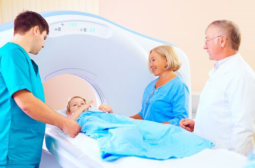
Children are significantly more sensitive to radiation than adults, and if exposed early in life, at levels found in computed tomography and even lower, leads to a measurable increase in cancer incidence as the children age into their 50’s and 60’s.
Exposure rate is the exposure produced per unit of time. The SI unit of exposure rate is the [C/kg .s] or (in old unit) [R/s]. In radiation protection, it is common to indicate these rate values “per hour” (e.g. R/h). In order to better understand the previously mentioned notions, we will take the example of an apple tree.

As shown in phase 1, the apple tree is considered to be a radiation source. The 3 apples falling down represent the radiation emitted by the radiation source. Now if we consider a girl sitting in the shade of the apple tree.

As shown in phase 2, only 1 of the 3 falling apples hits the girl’s shoulder. This apple represents the radiation that is transferred to the irradiated tissue represented by the girl’s shoulder. This explains the concept of the Absorbed Dose.
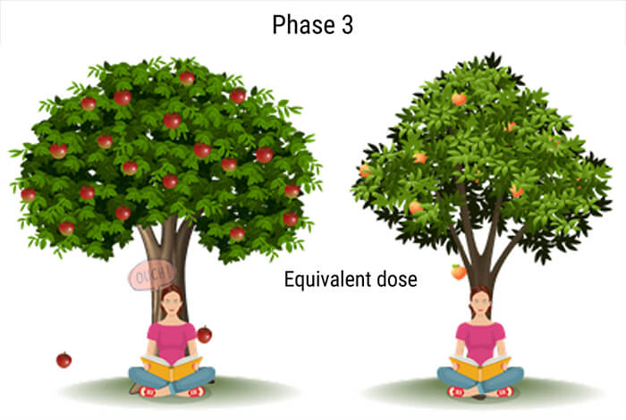
To go even deeper, a peach tree will represent another radiation source, thus the peaches will represent another type of radiation. The same girl is sitting in the shade of both trees.
As shown in phase 3, when one apple hits the girl’s shoulder, she reacts showing a painful expression. Whereas when one peach hits her shoulder, she barely reacts. The apple and the peach represent 2 different types of radiation that caused different effects on the same irradiated tissue. This explains the concept of the Dose Equivalent.
Finally, let us imagine, a bodybuilder sitting in the shade of the same apple tree just like the girl.
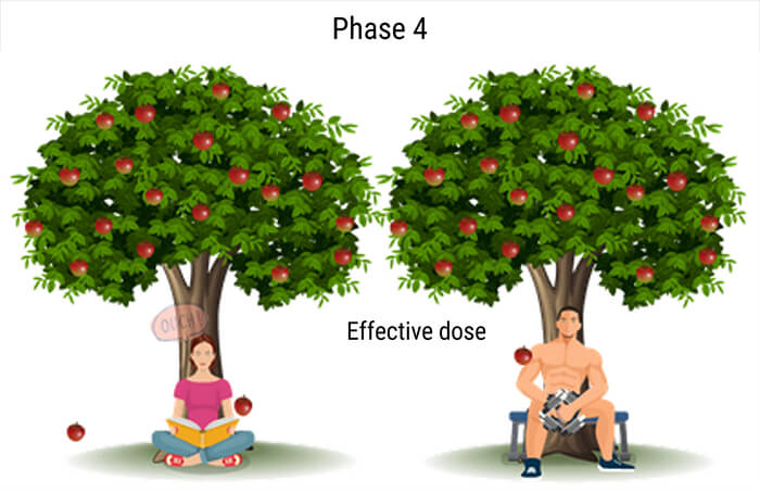
As shown in phase 4, when the same apple hits the bodybuilder’s shoulder, he does not express any reaction. Whereas the same apple caused a painful reaction for the girl. In this example, the same type of radiation caused different effects on 2 different types of irradiated tissues. This clarifies the concept of the Effective Dose that allows the comparison between 2 individuals.
Image gently is a campaign initiated on January 22, 2008 disseminates information on pediatric CT dose reduction among the various medical specialties. Its website contains a downloadable worksheet for the medical physicists to determine optimal technical factors for pediatric patients. Use of these techniques can reduce pediatric radiation doses by 50%.
The American College of Radiology (ACR) and the Radiological Society of North America (RSNA) formed a task force on adult radiation protection to address concerns about the increase of public exposure to ionizing radiation in medical imaging and called it imaging wisely.
Facilities have protocols for alert levels if that of which are exceeded the staff radiologist is informed and in conjunction with the medical physicist should carry out a dose estimate.
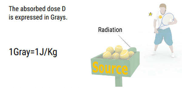
Absorbed dose is the quantity of energy imparted by ionizing radiation to unit mass of matter (such as tissue). Absorbed dose is expressed in a unit called gray, symbol Gy. One gray is equal to one joule per kilogram. Submultiples of the gray are often used such as the microgray, μGy, which is one-millionth of a gray. Absorbed dose was formerly expressed in a unit called the rad: 1 rad = 0.01 Gy.
Whereas exposure is defined for air, the absorbed dose is the amount of energy that ionizing radiation imparts to a given mass of matter. The absorbed dose is used to relate the amount of ionization that x-rays or gamma rays cause in air to the level of biological damage that would be caused in living tissue placed in the radiation field. The size of the absorbed dose is dependent upon the intensity (or activity) of the radiation source, the distance from the source to the irradiated material, and the time over which the material is irradiated. The activity of the source will determine the dose rate which can be expressed in rad/hr, mr/hr, mGy/sec, etc.
The dose rate is a measure of how fast a radiation dose is being received. Knowing the dose rate, allows the dose to be calculated for a period of time. For example, if the dose rate is found to be 0.8rem/hour, then a person working in this field for two hours would receive a 1.6rem dose.

Equal absorbed doses do not necessarily have equal biological effects: 1 Gy to tissue from alpha radiation, for instance, is more harmful than 1 Gy from beta radiation, because an alpha particle, being slower and more heavily charged, loses its energy much more densely along its path in tissue. Thus, to put all ionizing radiations on an equal basis with regard to potential for causing harm, another quantity is needed. This is the equivalent dose. It is expressed in a unit named the Sievert, symbol Sv. Equivalent dose is equal to the absorbed dose multiplied by a factor, called radiation weighting factor that takes account of the way a particular radiation distributes energy in tissue, thus influencing its effectiveness in causing harm. For gamma rays, X-rays, and beta particles, the factor is set at 1; therefore, the quantities are numerically equal. For alpha particles, the factor is 20, so that an absorbed dose of 1 Gy for alpha radiation corresponds to equivalent dose of 20 Sv. Submultiples of the Sievert are commonly used. Equivalent dose was formerly expressed in a unit called the rem: 1 rem = 0.01 Sv.
| Absorbed dose (Quantity of energy transferred to the matter per unit mass) |
Equivalent dose (Function type of radiation) |
Effective dose (Function type of tissue) |
| D = Etr / Mass (in J/Kg) Etr = Energy Trasnferred |
H = D x WR(in Sv) | E = Σ (H x Wt(in Sv) |
The quantity equivalent dose thus provide an index of the risk of harm from exposure of a particular tissue to various radiations irrespective of their type or energy. It is the basic quantity in radiation protection. However, the risk of fatal malignancy per Sv is not the same for the various tissues of the body: for instance, it is lower for the thyroid than for the lung. All these features can be dealt with by taking the equivalent dose in each of the major organs and tissues of the body and multiplying it by a tissue weighting factor related to the risk associated with that organ. The sum of these weighted equivalent doses is then called the effective dose. This quantity allows a variety of non-uniform distributions of equivalent dose in the body to be expressed as a single number, broadly representing the risk to health for any of the different distributions of equivalent doses. In general, effective dose can be considered to be a broad indicator of the risk to health from any exposure to ionizing radiation irrespective of the type and energy of the radiation. It applies equally to both external and internal radiations, whether the irradiation conditions are uniform or non-uniform.
In other words, the Effective dose E is an indicator of the risks of random effects that are not directly measurable; it expresses the total irradiation in terms of the overall exposure of the entire body using weighting factors related to tissue radiosensitivity (Wt).
It is expressed in Sievert or Millisievert (mSv) and it realizes a true integration of the rate for the whole organism, for each exposure, even partial.
Please note that it is difficult to make a direct measurement of organ dose or effective dose in a patient, thus there is a need to a quantity that can be used to estimate them, but can be measured easily. The most useful quantities in radiography are the Entrance surface dose (ESD) and the Dose-area product (DAP).
KERMA (Kinetic Energy Released per unit Mass) is the energy transferred to electrons by photons and can be expended through collision interactions (soft collisions and hard collisions) and through radioactive interactions (bremsstrahlung and electron–positron annihilation).
- Applies to photons (x and gamma) only
- Only concerned with the first stage of energy transfer – from photons to electrons
- In practice, it is equal to the absorbed dose in the diagnostic radiology energy range
- Unit is the gray
- Air kerma is the kerma measured in air
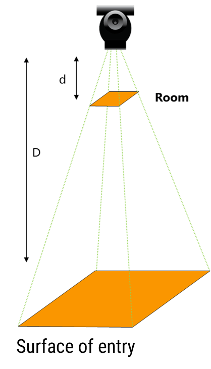
For a radiological examination, the dose-area product (DAP) is recorded. For that measurement, the system consists in a flat and sufficiently large ionization chamber to intercept the entire examination beam. The apparatus measures the product of the beam area and dose delivered which is constant irrespective of where the measurement is made. The dose-meter is usually located at the level of the collimator (diaphragm) of the installation.
DAP = Air KERMA x Beam Area
The effect of a single exposure differs depending on whether a region or the whole body is irradiated (the same dose may be fatal in the latter case and harmless in the former case).
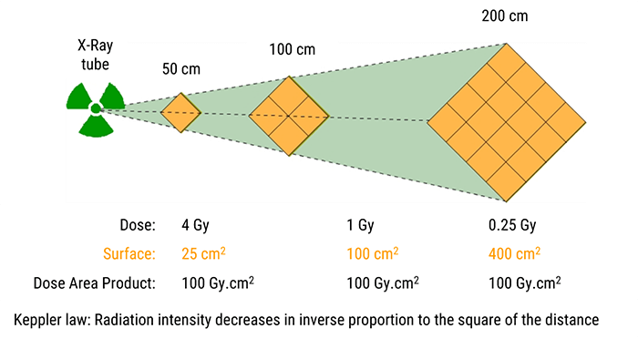
The exposure distance is not included in the calculation of the DAP since, according to Keppler’s law, the intensity of radiation decreases as a function of the square of the distance. Between the chamber and entry surface, the dose is proportional to d/D but the area increases with the distance as per D2/d2. It all cancels out.
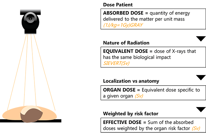
To summarize the concepts of radiation measurements and dose relationships, here are some general definitions:
- The absorbed dose is defined by the quantity of energy delivered to the matter per unit mass
- The equivalent dose is the dose of X-rays that has the same biological impact and is measured in Sievert
- The organ dose is the equivalent dose specific to a given organ
- And finally, the effective dose which is the sum of the absorbed doses weighted by the organ risk factor
Sources of Ionizing Radiation
Now that we have covered radiation physics, explained why radiation protection is required, and defined the different radiation dose measurements, let’s continue with a discussion covering the different sources of ionizing radiation.
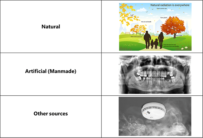
From the beginning, life has evolved in a world containing significant levels of ionizing radiation. The principal sources of natural radiation are: cosmic rays, which impinge on the Earth from outer space; terrestrial radiations, which are released by the disintegration of thorium, radium, uranium, and other radioactive minerals in the Earth’s crust; and internal radiations, which are emitted by the disintegration of potassium-40, carbon-14, and other radioactive isotopes that are normally present within living cells.
In addition to natural background radiation, humans are exposed to radiation from various man-made sources, the largest of which is the application of X-rays in medical diagnosis.
And finally, the less significant artificial sources of radiation include radioactive minerals in crushed rock, building materials, and phosphate fertilizers; radiation-emitting components of television sets, smoke detectors, and various other consumer products such as radioactive fallout from nuclear weapons; and radiation released in nuclear power production.
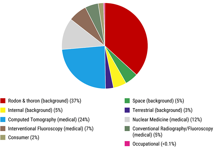
As we mentioned in the previously, there are many sources of ionizing radiation with radon being the highest background radiation source and computed tomography being the highest medical source to persons.
This chart shows that medical sources of radiation account for about 48%, while Radon and Thoron account for 37% of the total annual dose received by people.
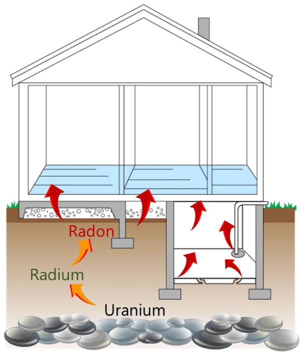
Radon is an odorless and colorless radioactive gas that is produced by the decay of uranium-238. It is an inert gas, meaning that it does not react with surrounding matter, and can move up through the ground and into the atmosphere. It is the second leading cause of lung cancer in America. For this reason, the EPA has set guidelines for maximum environmental radon levels based on limiting the risk of developing lung cancer from radon exposure. It recommends remediation at a maximum of 4 picocuries/liter (pCi/L) of radon in air.
Radiation Effects
Effects increase with increasing dose:
| Dose in Sv | Effects observed |
| 0.25 | Suppression of blood components |
| 1.5 | Nausea, diarrhea |
| 2 – 6 | Redening of the skin (erythema) |
| 2.5 | Gonads = temporary sterility |
| 3 | LD 50/30 |
| 6 | Death |
Now that we have covered the different sources of ionizing radiation, it is important to know that its effects on the humans increase with increasing radiation dosage. A dose of just 0.25 Sv causes suppression of blood components. Doses to near 1.5 Sv cause the first signs of radiation thickness including nausea, vomiting, and diarrhea. Doses between 2 and 6 mSv cause erythema and doses above 6 Sv cause cell death.
Normal skin exposures from diagnostic x-radiation for a PA Chest is 0.1 mGy while normal skin exposures for an AP Abdomen is 4 mGy. Normal gonadal doses from diagnostic procedures are listed as follows:
| Diagnostic Procedure | Gonadal dose in mGy |
| Chest | < 1 |
| Abdomen | 1.25 |
| Pelvis | 1.5 |
| Lumbar spine | 2.25 |
Fundamental Principles
What are the fundamental principles of radiation protection?
Current guidelines are based on the conservative assumption that there is no safe level of exposure. In other words, even the smallest exposure has some probability of causing a stochastic effect, such as cancer. This assumption has led to the general philosophy of not only keeping exposures below recommended levels or regulation limits but also maintaining all exposure “as low as reasonable achievable” (ALARA). The ALARA principle is a basic requirement of current radiation safety practices. It means that every reasonable effort must be made to keep the dose to workers and the public as far below the required limits as possible.
The manager must justify the intervention to avoid unnecessary doses, and the investigator must use the optimum methods and working principles (preparation, instrumentation, protection) to optimize the intervention.
In other words, radiation protection is defining individual and collective radiological constraints to limit patients and workers’ doses (workstation studies). The term ORP is synonymous with ALARA.
The radiation safety officer (RSO) is charged by hospital administration with being directly responsible for the execution, enforcement, and maintenance of the ALARA program throughout the facility.
Hormesis
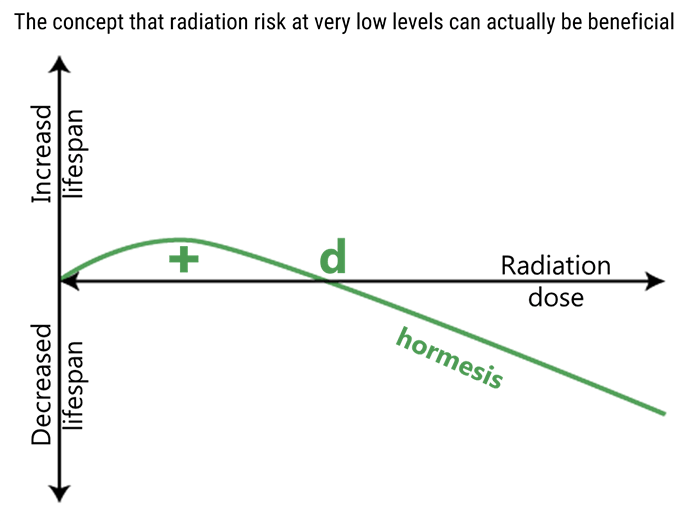
Exposure to high levels of ionizing radiation is extremely bad for human health, however, evidence that’s been trickling in since the nuclear age suggests that LDR could actually benefit human health. The concept of radiation hormesis is that there exists a beneficial aspect to groups of individuals from continuing exposure to small amounts of radiation.
In this figure, radiation hormesis is illustrated by the green line. Low dose radiation (less than “d”) can have a beneficial effect on biological systems, while at high doses (greater than “d”), the effect is negative.
Report No. 5 of the National Academy of Science on Biological Effects of Ionizing Radiation (BEIRV) is based upon extrapolations from radiation EqDs greater than 0.5 Sv. It expounds that lifetime survival data possibly appears to indicate that Japanese atomic bomb survivors with moderate radiation exposure of 5 to 50 mSv, which is the equivalent to 1.5 to 15 years of natural radiation, have a reduced cancer death rate compared with a normal exposed control population. Until this theory is proven, the medical radiation industry will continue to follow the principles of ALARA and the no-threshold concept.
Dose Limits
The following are the maximum suggested radiation doses and dose limits set forth by the NCRP.
- Minimum sensitivity of OSL badges – (0.01 mSv)
- Minimum sensitivity of film badges – (0.01 mSv)
- Minimum sensitivity of TLD – (0.05 mSv)
- Occupational exposure-annual dose equivalency – (50 mSv)
- Dose equivalency for the lens of the eye – (150 mSv)
- Dose equivalency for extremities, others – (500 mSv)
- Education and training exposure (under 18) – (1 mSv)
- Embryo-fetus exposure-monthly – (0.5 mSv)
- Cumulativfe exposure – (age x 10 mSv)
Protective Equipment and Requirements
Also included here are the minimum equipment requirements and minimum lead equivalents for protective equipment.
Protective Equipment
- Aprons for fluoro – (0.5 mm of lead above 100 kVp)
- Gloves – (0.25 mm of lead)
- Thyroid Shield – (0.5 mm of lead)
- Glasses – (0.35 mm of lead)
- Waer protective aprons and gloves – (5 mR/hr)
Equipment Requirements
- Primary protective barrier – (7 ft high and 1/16″ lead)
- Secondary barrier – (1/32″ lead equiv.)
- Protecdtive drape in fluoro – (0.25 mm lead equiv.)
- Bucks slot cover – (0.25 mm lead equiv.)
- Mobile exposure cord – (6 ft from pt, tube, and useful beam)
- Source to skin distance – (15″ of 30 cm)
- Leakage radiation must not exceed – (1 mGy/hr at 1 meter)
- Fluoro exp. rate limits – (100 mGy/min at tabletop)
In this section, we will learn about various interactions of x-ray and matter, and describe the relationship between kVp and patient occupational dose. First we need to understand the production process of x-rays.
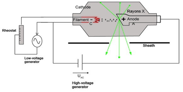
Interactions within the X-Ray Tube
The activation of the exposure switch by the radiographer produces specific reactions inside the x-ray tube.
Pitch
Electrons are thermionically emitted from filament of cathode towards the target on the anode. X-rays are produced when the electrons are suddenly decelerated upon collision with the metal target; these x-rays are commonly called bremsstrahlung.
If the bombarding electrons have sufficient energy, they can knock an electron out of an inner shell of the target metal atoms. Then electrons from higher states drop down to fill the vacancy, emitting x-ray photons with precise energies determined by the electron energy levels. These x-rays are called characteristic x-rays.
To better understand the difference between the named types of X-rays, we will explain the two interactions that may occur in the X-ray tube and trigger their production.
The first one is the Bremsstrahlung interaction in which an incident electron interacts with the force field of the nucleus, causing the incident electron to slow down, thus diverting the electron’s course. The electron loses energy and changes direction.
Two interactions may occur:
- 1 – Bremsstrahlung interaction

- 2 – Characteristic interaction
The second one is the characteristic interaction, where characteristic X-rays are produced when an element (anode target) is bombarded with high-energy particles, which can be photons, electrons or ions (such as protons). When the incident particle strikes a bound electron (the target electron) in an atom, the target electron is ejected from the inner shell of the atom.
Interactions within the Patient’s Body
Now that we know how the X-rays are produced, let us study their interaction with the matter within the patient’s body.
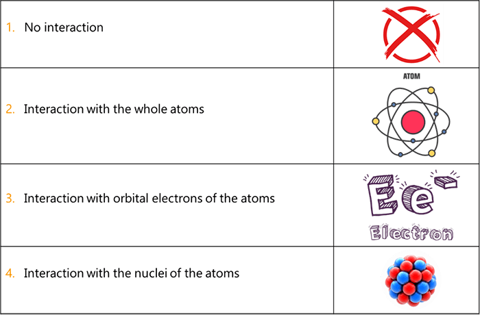
The photons in the useful beam will interact with matter in the body in the following manners:
- Some of the photons will pass through the body with no interaction and head directly to the IR (Exit)
- Some photons will interact with the whole atoms and cause them to be excited, but will not be able to ionize the atoms
- Some of the photons will interact with orbital electrons of the atoms and eject them from their orbit
- Extremely high energy photons such as those used in radiation therapy, will be capable of interacting with the nuclei of atoms
- In diagnostic radiography, the interactions between the X-ray photons and the patient’s body will most often occur with orbital electrons
When x-ray photons actually interact with matter in the body (number of x-ray photons in the useful beam is reduced) and do not pass through directly to the Image. Receptor, they tend to do one of two things:
- Scattering: The x-ray photons can interact with the atoms, lose some of their energy and change direction and go on as a photon with less energy and with a new direction. This is known as a scatter interaction. This new scattered photon may then go on to interact with other atom(s) and scatter again or be totally absorbed
- Absorption: When an x-ray photon is absorbed, no radiation exits the body from that photon, all of its energy is transferred to the matter and the x-ray photon ceases to exist
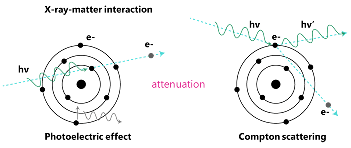
As the X-ray useful beam passes through the body, the number of X-ray photons is reduced; this fact introduces the term “Attenuation”; so what does it mean?
Attenuation results in the loss of energy as the beam passes through the body and interacts with various matters within the body. It can happen through two interactions: the Photoelectric and the Compton effects.
The likelihood of one interaction occurring over another varies, depending on the incident photon’s energy and the atomic number of the matter. We will speak more on these 2 types of interactions shortly.
We state that x-rays interact at these various structural levels through five mechanisms:
- The Coherent Scattering Effect predominates at energies below 10 keV
- The Photoelectric Effect predominates at low energies, between 1 keV and 50 keV
- The Compton Effect predominates at high energies, between 20 keV and 150 keV
- The Pair Production predominates at energies above 1.02 MeV
- And the Photodisintegration predominates at energies above 10 MeV
These are Interactions with matter and their energy levels. We will explain each mechanism separately, and thus we will start by the first one which is the coherent effect.
When x-rays with very low energy levels of less than 10 keV interact with tissues or matter in the body, Coherent Scatter is produced. Please note that the coherent effect is also known by classical scatter, unmodified scatter, Thompson scattering (Rayleigh), and elastic scatter.
In this type of interaction between x-rays and human matter, the incident photon interacts with the electron(s) of the atoms and excites them. The excited or vibrating atoms then release this energy as another x-ray photon or scattered x-ray photon of the same energy of the original x-ray, but traveling in a slightly different direction.
Most of the time, these scattered photons move in a forward direction. They do not help with image production and if they do reach the IR, they may contribute to image fog or image noise (digital) or general “graying” of an image leading to a reduction in image contrast. There is no ionization of the atoms in the tissue in the case of a Coherent Effect.

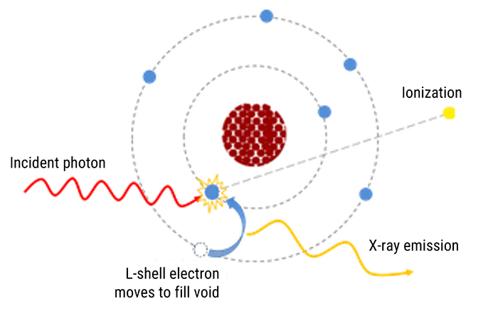
Moving to the Photoelectric effect or Absorption, this effect occurs when an x-ray photon interacts with an inner shell electron (K or L shell) of an atom in the patient’s body. The incident x-ray photon energy must be slightly greater than the binding energy of the electrons in one of these shells.
The incident x-ray photon ejects the inner shell electron and the energy of the x-ray photon is totally absorbed during the interaction. The result is an ionized atom and ejected electron called the photoelectron. Please note that there is no scatter radiation with the Photoelectric Effect.
The photoelectric effect is crucial to the formation of the radiographic image, and is responsible for the production of contrast in the image. The photoelectron has a kinetic energy level equal to the difference of the energy of the incident photon minus the binding energy of the shell from which it exited. So, it becomes a high-speed electron which takes off to collide with another atom and is usually absorbed within 1 or 2 mm of soft tissue.
Therefore, there is no additional radiation energy left neither from the incident photon nor the photoelectron to reach the image receptor. The photoelectric absorption will occur with inner-shell electrons that are tightly bound when the x-ray photon energy is just slightly higher than the electron binding energy.
If the x-ray energy is too much higher than the binding shell energy of the K-shell or L-shell of an atom, the photon is more likely to penetrate the tissue without an interaction. As the atomic number of the tissue or material increases as in bone or contrast material, the incoming electron has a better chance of being absorbed photo-electrically.
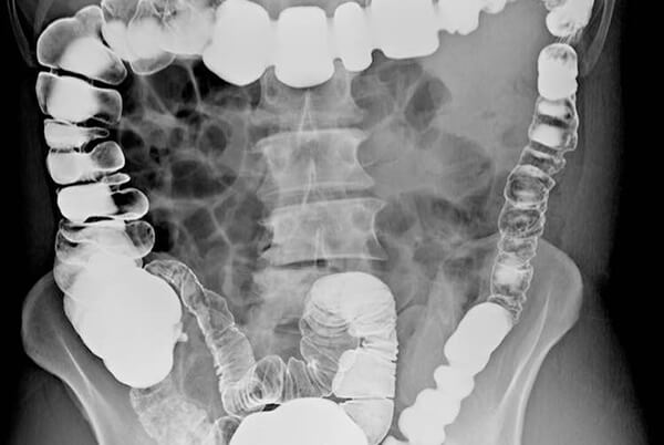
As an example, when we image the intestines in the abdominal area without contrast media, we will get very little intestinal detail, as the differences in tissues in that area are very little. When we introduce, barium, however, the barium lined intestines will absorb the x-ray photons with a setting of 110 kVp, while the surrounding non-filled barium tissues will be over penetrated, leaving a darker background against the white intestines.
The same is true when we consider the thorax with tissues of different mass densities and atomic numbers. The air in the lungs is a gas that has a low density (concentration of mass or molecules within a given volume of space). The x-ray photons will pass right through the air and directly to the image receptor. The soft tissue in the lungs will absorb some of the low-energy x-rays in the beam and will appear less dark as compared to the areas with the air. Finally, the ribs will absorb even more of the x-rays and will then appear white on the image.
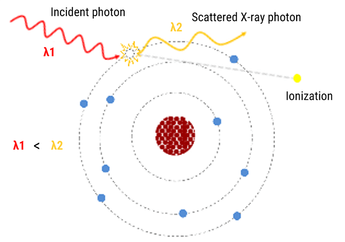
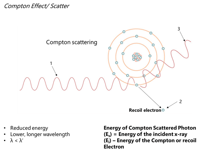
Now that we know quite well about the Photoelectric Effect, let us discuss the Compton Effect. As x-ray photons move into the diagnostic range of 20 keV to 150 keV, some of the x-rays produced in the useful beam will interact with and remove loosely bound outer-shell electrons of the tissues in the body of the patient. This process is known as the Compton Effect or Compton Scattering. Two basic processes occur with such a reaction:
- First, the outer-shell electron is ejected
- Second, the production of a scattered x-ray photon with a reduced energy compared to the incident x-ray photon and traveling in a different direction than the incident x-ray photon
The x-ray scattered photon that exits the atom at a different direction is called the Compton Scattered Photon. The Compton Scattered Photon possesses less energy than the incident photon and possesses lower frequency and longer wavelength.
Compton Scattered Photon retains most of the energy because it took very little energy to eject an outer-shell electron. Thus, the Compton Scattered Photon has a possibility of interacting with other atoms until it is eventually totally absorbed in a process called photoelectric absorption which we discussed previously.
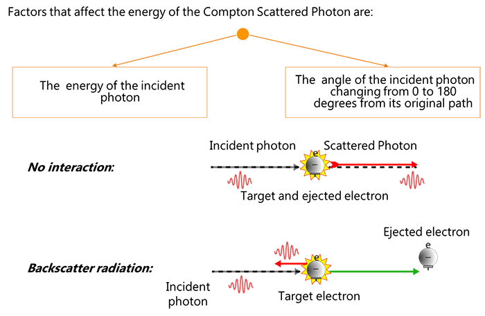
The energy of the Compton Scattered Photon is affected by the energy and the angle of the incident photon (changing from 0-degrees to 180-degrees from its original path). As the energy of the incident photon rises, the energy of the Compton Scattered Photon rises as well.
When the angle of the incident photon is 0-degrees, no energy is given to the electron. However, at 180-degrees, more energy is transferred to the electron and the x-rays are scattered back in the direction of the incident x-ray photon. We call this backscatter radiation. This radiation bounces off walls or the examination table, not from the patient.
Most of the Compton Scattered Photons are forward moving and move toward the IR and provide no useful information on the radiograph. They produce a uniform density on film and a uniform intensity on digital radiographs that result in reduced image contrast.
During fluoroscopy, Compton Scatter from the patient is the source of most of the occupational radiation exposure that radiographers receive! It is less of an issue in general radiography as we are not usually in the room.
The recoil or Compton Electron is available as a free electron to fill a shell- “hole” from another ionization event. Compton Effect can occur in soft tissue atoms through the atoms of bone. In other words, Compton Scatter is an issue throughout the diagnostic range.
Moving forward, we will now explain the Pair production mechanism. In the body, when x-rays with energy levels of 1.02 Mev or higher approach the nuclear field of an atom in the patient’s body, the x-ray photon actually disappears and its energy is converted to matter in the form of two electrons that are emitted from the nucleus: a positive electron called a Positron and a negative electron called a Negatron.
We call this process “Pair Production” as we have created a pair of electrons with different charges. The negatron is absorbed or combined with another atom with a vacancy just like any other free electron in the body.
The positron, however, is much more volatile because it is simply unnatural. It immediately looks to combine with another nearby negative electron. When it forms this union, its energy is given off in the form of two photons called gamma rays, that originate from the nucleus of an atom, each having an energy of 0.51 MeV or higher.
So, when the positron combines with a nearby electron, the reaction causes the two particles of matter to disappear and 2 photons to appear. This process where matter is converted back to energy is known as an annihilation reaction. Pair production is the basis of Positron Emission Tomography used in Nuclear Medicine. It is also used in Radiation Therapy.
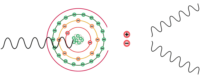
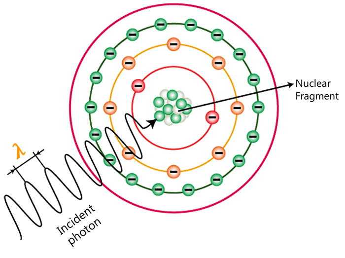
And finally comes the Photodisintegration. When x-ray photons get to the range of energy of 10 MeV, another process occurs. When x-ray photons get to the range of energy of 10 MeV, another process occurs. The excitation of the nucleus due to the absorption of the energy causes the nucleus to emit a nucleon or other nuclear fragment. The excitation of the nucleus due to the absorption of the energy causes the nucleus to emit a nucleon or other nuclear fragment.
Now that we understood the different mechanisms of interaction that can happen between the X-ray photons and the matter, we will end this section by explaining the concept of the Differential Absorption.
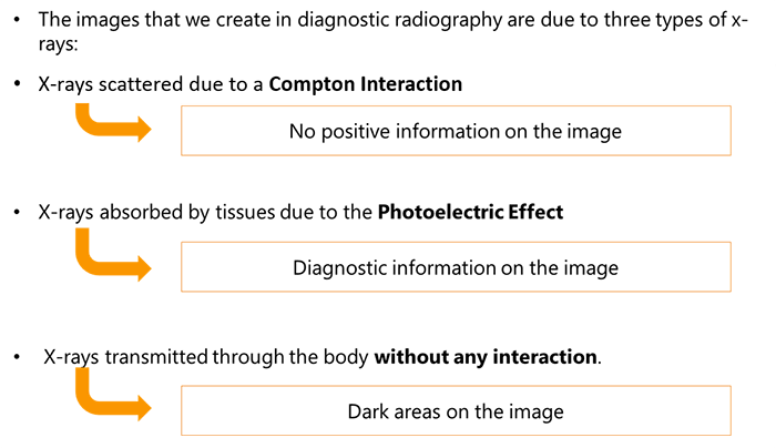
The images that we create in diagnostic radiography are due to three types of x-rays: X-rays scattered due to a Compton Interaction, X-rays absorbed by tissues due to the Photoelectric Effect, and finally X-rays transmitted through the body without any interaction.
As we mentioned previously, the Compton Scattering does not contribute any positive information on the image. It either “fogs” the image in film/screen or creates “image noise” or overall “dulling” of the image in digital images. We use grids or other techniques to try to eliminate much of the Compton Scatter from reaching the image.
The Photoelectric Absorption provides diagnostic information to the image receptor. Because these x-rays do not reach the image receptor, they represent anatomical features with high x-ray absorption characteristics; such as bone, metal or contrast filled structures. These appear white on our image.
X-rays that penetrate through the body and head directly to the image receptor produce dark areas on our radiograph and represent structures that are radiolucent, such as air in the lungs. So, our image that we produce is a result of the differences in x-rays absorbed photoelectrically in the patient and those transmitted to the image receptor. This difference in x-ray interaction is known as differential absorption.
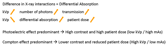
The Differential absorption increases as we decrease our kVp so we need to be careful when we make our technical factor selection on our control panel. As kVp is increased, the total number/quality of x-ray photons transmitted through the patient without interaction increases. So more transmission through tissue.
The problem is that as we decrease our kVp to increase differential absorption, we also increase outpatient dose, due to the secondary radiation created in the photoelectric interactions. So we need to be as precise as possible and keep in mind the type of tissue we are trying to image.
When we choose a kVp in the range of 40 to 70 kVp, we produce a maximum number of photons in the useful beam with energies in the range of 25 to 45 keV. This will allow us to demonstrate boney structures versus soft tissue effectively.
When we try to outline internal organs we use contrast material with higher atomic numbers than that of bone and soft tissue. Thus, in this limited condition it is necessary to raise the kVp so that the majority of the photons in the useful beam will be of a level to effect photoelectric absorption. In this situation raising the kVp level to 90 or above will still provide the photoelectric interaction that we desire.
Likewise, if the tissue being irradiated is very dense, i.e. the quantity of matter in a given volume is very high, and we may be able to affect more photoelectric absorption with a higher kVp. An example would be the skull or the femur where we utilize higher kVp levels than when we radiate the hand
When photoelectric is predominant, the images will have high contrast (black + white) due to complete absorption without undesirable scatter. We use low kVp/high mAs to produce such images. The problem is patient dose. When Compton interactions prevail, the images will have lower contrast or more shades of gray. We use high kVp/low mAs techniques to reduce patient dose.
In the following section, we will focus on the principles of radiation protection in the operating room and the dangers and risks related to radiation exposure. First let’s start by introducing the evolution of surgeries through the history and the integration of medical imaging in the Operating Room.

The very first surgeries in history, before radiology or even anaesthesia, were very invasive and traumatizing; cutting into the body to alleviate sickness brought the possibility of infection or even death, and promised excruciating pain.
Wilhelm Roentgen (1845-1923) created a surgical revolution with the discovery of the X-rays in late 1895: shortly after his discovery, Roentgen found that X-rays would pass through human tissue, rendering the bones and tissue beneath visible. News of his discovery spread worldwide, and within a year, doctors in Europe and the United States were using X-rays to locate gun shots, bone fractures, kidney stones and swallowed objects. Subsequently, this technique was introduced in the management of surgical patients and imposed itself in all kinds of surgeries.
The integration of medical imaging in the operating room enabled safer and minimally invasive procedures with better results.
The Implication of Medical Imaging in the Operating Room
What are the different types of Radiography and Fluoroscopy equipment utilized in the OR?
A Hybrid Operating Room is an advanced procedural space that combines a traditional operating room with an image guided interventional suite. This combination allows highly complex advanced surgical procedures. Not only are the rooms combined, but the teams as well, to form a multi-disciplinary group of clinicians, prepared to meet the complex needs of the patients.
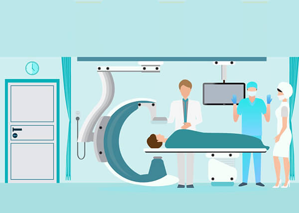
A Hybrid Operating Room is an aseptic environment that combines surgical equipment, instruments, surgical tables, operating room lights, equipment management systems, and surgical booms, along with fixed advanced imaging systems such as fixed C-Arms, CT scanners, and MRI machines. This combination offers the capability to perform combined image-guided procedures with minimally invasive surgeries that are intended to be less traumatic for the patient by minimizing the incisions.
This kind of surgeries require the preparation of proper radiation safety protocols, dedicated to protect the Medical Radiographer, the rest of the staff, and the patient from radiation exposure.
What is a Hybrid Operating Room?
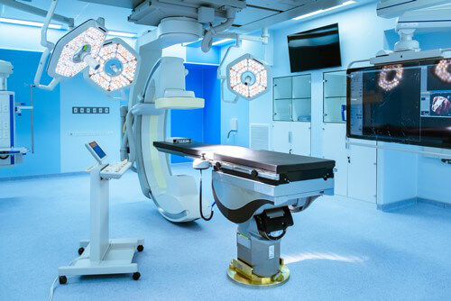
Radiography and Fluoroscopy equipment used in the OR can be fixed or mobile. The fixed equipment is permanently installed in the OR while the mobile equipment can be used in different departments such as the Intensive Care units.
First, let us describe the fixed equipment. The Radiography or Fluoroscopy equipment can be fixed in the OR either to the floor or the ceiling. Static radiographic studies in the OR are used for a variety of both interventional and surgical procedures.
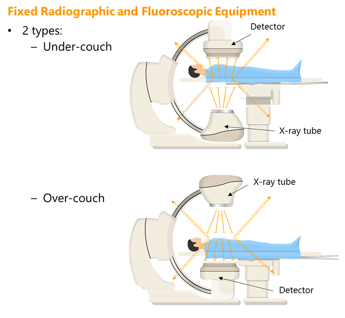
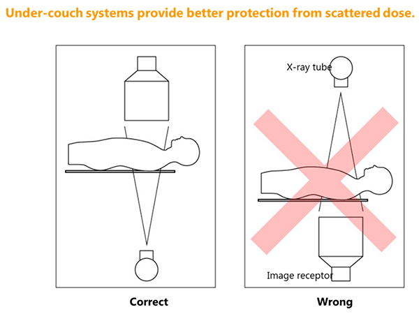
Two types of fixed equipment can be found: Over-couch and Under-couch systems. The categorization depends on the position of the X-ray tube and the detector in relation to the OR table.
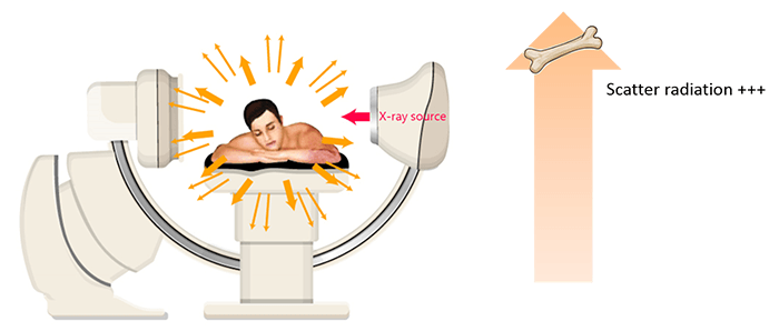
The over-couch configuration consists of an X-ray tube installed over the OR table; in this case, the detector is under the table facing the tube. The under-couch configuration consists of an X-ray tube installed under the OR table; in this case, the detector is over the table facing the tube.
The main concern during radiographic or fluoroscopic studies in the OR is the radiation exposure of the staff. This reveals the main difference between the over-couch and the under-couch configurations, which is related to the anatomical area of the staff member’s body that receives the most radiation exposure depending on the position of the X-ray tube.
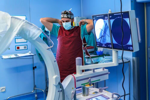
Moving to the mobile radiography equipment, acquiring radiographic images during the surgical procedures using this type of equipment presents special challenges to make sure prudent radiation safety practices are in place: standard radiology departments are well designed for that purpose, unlike the OR, which requires additional measurements.
These measurements and safety practices are the responsibility of the medical radiographer who should make sure that the staff, as well as the patient, are efficiently protected from unnecessary radiation exposure.
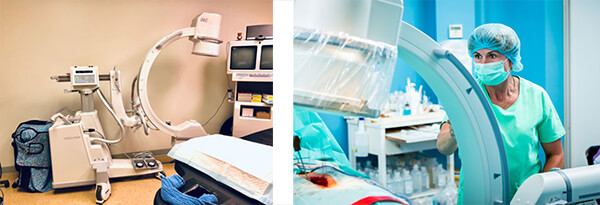
Last but not least, comes the mobile fluoroscopy equipment. Portable fluoroscopy imaging is possible in the operating room thanks to the Mobile C-arm units. The C-arm equipment has a special configuration: it consists of a curved arm shaped like the letter “C”. The fluoroscopic X-ray tube is mounted on the bottom curve, whereas the image intensifier is mounted on the top curve.
A C-arm equipment can be used to acquire static radiographic images, as well as real-time fluoroscopy. Features on newer mobile C-arm systems include 3-D navigation aids and image processing software to improve image quality and system capabilities. Some systems offer technologies to reduce the radiation dose delivered to patients. Other features include a touch-screen interface, laser aiming guides, digital subtraction angiography (DSA) and procedure road-mapping, allowing vascular procedures to be planned with minimum amounts of contrast media and shorter fluoroscopy times.
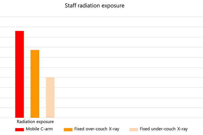
Now that we know the different types of imaging equipment that can be found in the OR, let us compare the staff radiation exposure related to each type. Staff radiation exposure is actually higher while using mobile C-arm units and fixed over-couch x-ray systems compared to fixed under-couch x-ray systems.
Radiation Measurements
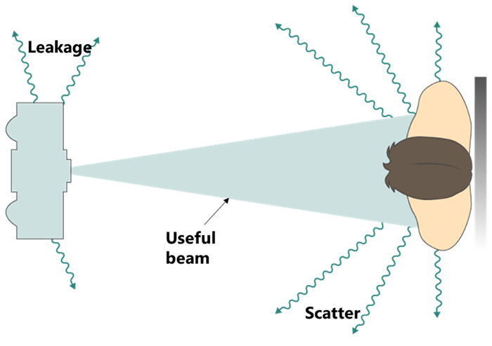
Scatter Radiation
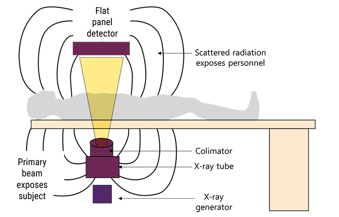
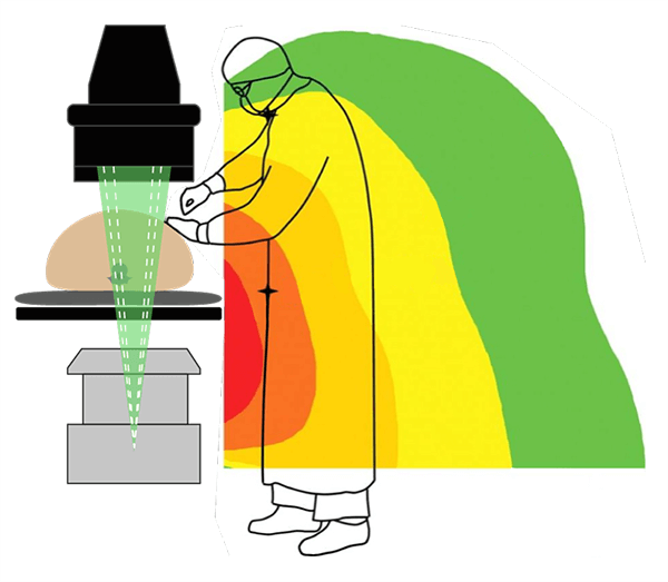
Scatter radiation is a type of secondary radiation that occurs when the beam intercepts an object, causing the X-rays to be scattered. During most imaging procedures, the patient’s body is the object that deflects the radiation and causes it to scatter around the room.
The human body is composed of 4 biologic densities. If we want to order these according to increasing subject density, air would be in the top of that order, followed by fat, water, and then bone. The amount of scatter radiation increases with the increasing tissue density. For instance, bony structures result in more scatter radiation than muscles.
The majority of radiation exposure from medical imaging procedures performed in the OR comes from scatter radiation from the patient. As a general rule, at 3.3 feet from the patient, the intensity of scatter radiation is 0.1% of the intensity of the primary beam at the patient. The primary beam is the most intense on the entrance side with the greatest amount of scatter radiation occurring on the tube side.
Radiation Dose Metrics specific to Fluoroscopy
Let’s go deeper into the radiation dose metrics that are specific to the Fluoroscopy. According to the National Council on Radiation Protection and Measurements, radiation dose to the US population had risen dramatically since the early 1980s. One of the biggest reasons is that the fluoroscopically guided interventional procedures are in continued growth which caused the fluoroscopic exposure times to soar.
Four metrics have been developed for radiation dose estimation in fluoroscopic procedures:
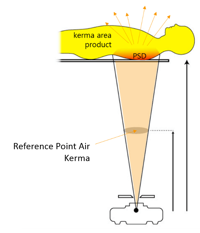
- Peak Skin Dose (PSD)
- Reference Poist Air Kerma
- Kerma Area Product
- Fluoroscopy Time
The ISI measurement for exposure to ionizing radiation from fluoroscopy is air kerma. Air kerma measures the amount of energy transferred to the air by the radiation field at a point. When scatter radiation is excluded, this value equals absorbed dose, measured in Gray.
Four metrics have been developed for radiation dose estimation in fluoroscopic procedures: the Peak Skin Dose, the Reference Point Air Kerma, the Kerma Area Product and the Fluoroscopy Time. Let us explain each of the 4 metrics.
- Peak Skin Dose is the highest radiation dose received by any local area of the patient’s skin during a procedure. PSD includes contributions from both the primary x-ray beam and the scatter radiation. It is highly dependent on instantaneous dose rate and how long the x-ray beam is directed at a specific body area
- The Air Kerma accumulated at a specific point in space in relation to the fluoroscopic gantry is called the Reference Air kerma. It is measured in Gray and does not include backscatter radiation
- Kerma area product is similar to the surface integral exposure and the total radiation delivered to a patient during a fluoroscopy procedure. It increases with the increasing Peak Skin Dose and is most often used to estimate stochastic risk. It provides a good estimation of the total radiation energy delivered to a patient during a procedure. It may be measured with a dosimeter or determined by internal calculations of the fluoroscopic unit.
- The fluoroscopy time refers to the total time fluoroscopy is used during a procedure and is measured from the start to the end of x-ray production.
Recommended Radiation Dose Thresholds
This section gives an overview about the process of determining the dose thresholds and details the recommended radiation dose thresholds in fluoroscopy units. Who is eligible to set the recommended radiation dose thresholds, and how are these values determined?
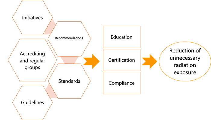
Various accrediting and regular groups such as the International Commission on Radiological Protection (ICRP), the National Council on Radiation Protection (NCRP), Nuclear Regulatory Committee (NRC), National Cancer Institute (NCI), and the American Association of Physicists in Medicine (AAPM) are focusing on reducing unnecessary radiation exposure through radiation education, certification, and compliance by establishing initiatives, recommendations, standards, and guidelines.
| NCRP | NRC | CFR | CDRH-FDA |
| Sets the maximum dose limits Reviews the recommended dose limits |
Mandates the monitoring of the exposed workers | Governs the maximum exposure rates permitted in the USA | Oversees the maximum exposure rates permitted in the USA |
The NCRP sets and continuously reviews the maximum dose limits. The NRC mandates that all workers who are exposed to radiation be monitored so they do not exceed the maximum dose limits.
The maximum exposure rate permitted in the United States is governed by the Code of Federal Regulations (CFR) and is overseen by the Center for Devices and Radiological Health-Food and Drug Administration (CDRH-FDA).
| ICRP dose thresholds | Before April 2011 | After April 2011 |
| Lifetime eye dose threshold for cataract induction | 2000 mSv | 500 mSv |
| Occupational annual dose limit | 150 mSv | 20 mSv average over 5 years and maximum 50 mSv/year |
In April 2011, the ICRP revised its lifetime eye dose threshold for cataract induction downward, from 2000 mSv to 500 mSv, and the occupational annual dose limit from 150 mSv to 20 mSv, averaged over a defined period of 5 years, with no single year exceeding 50 mSv.
Now let us go into the details of the specific dose thresholds for Fluoroscopy units. In accordance with the FDA and the International Electrotechnical Commission (IEC), every fluoroscopic equipment that is manufactured after June 2006 shall be able to display the dosimteric quantities as well as the cumulative fluoroscopic time (FT). The recommended radiation dose thresholds for the 4 previously explained metrics that are specific to fluoroscopy are as follows:
| Recommended Radiation Dose Thresholds | |
| Dose Metric | Threshold |
| Peak Skin Dose | 3000 mGy |
| Reference Dose | 5000 mGy |
| Kerma Area Product | 300,000 to 500,000 mGy.cm2 |
| Fluoroscopy Time | 40 to 60 min |
For fluoroscopic equipment manufactured after June 2006, the FDA and the International Electrotechnical Commission (IEC) require the display of the dosimetric quantities and cumulative fluoroscopy time (FT).
Dangers and Risks related to the Radiation Exposure
Moving to the dangers and risks related to the radiation exposure; in this section, we will define and show the difference between biological, stochastic and deterministic effects. To begin, it is important to mention that during a fluoroscopic procedure in the OR, the patient and the surgeon receive the most radiation. They are followed by the first assistant and the anesthesiologist in the second place, and then the nurse who is less exposed to radiation than the others.
Now let’s differentiate between the different types of biological effects associated with radiation exposure.
When high-energy particles or electromagnetic waves encounter living cells, they can cause heating, break chemical bonds, or ionize molecules. The most serious biological damage results when these radioactive emissions fragment or ionize molecules. For instance, alpha and beta particles emitted from nuclear decay reactions possess much higher energies than ordinary chemical bond energies. When these particles strike and penetrate matter, they produce ions and molecular fragments that are extremely reactive. The damage this does to biomolecules in living organisms can cause serious malfunctions in normal cell processes, taxing the organism’s repair mechanisms and possibly causing illness or even death.
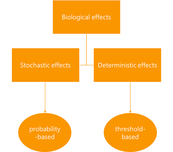
Biological effects resulting from radiation exposure are divided into stochastic and deterministic effects. The stochastic effects are probability-based while the deterministic effects are threshold-based. Shielding devices are imperative for radiation safety and protection of the staff.
What do we mean by “Stochastic effects”?
The stochastic effects originate from damage to single cells that is sufficient enough to cause a mutation but does not impair the cell’s division. An example of the stochastic effects is the radiation-induced cancer.
The stochastic effects are based on the probability that a given radiation exposure may damage genes that trigger cancer or increase the risk of developing cancer. Therefore, two types of risks must be addressed: the likelihood of an adverse outcome and the severity of such an outcome.
As mentioned previously, the stochastic effects are based on the probability that a given radiation exposure may damage genes, however, the deterministic effects are characterized by a threshold dose, and the effect does not become visible until the threshold dose is exceeded, at which point the extent of the damage or injury intensifies with increasing dose.
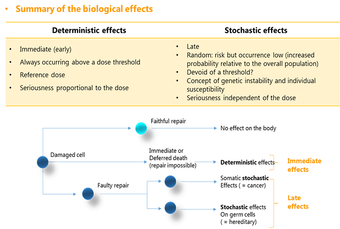
They result from damage to multiple cells that may be severe enough to cause cell sterilization or death. To summarize the biological effects of radiation exposure, this table shows a brief comparison between the stochastic and the deterministic effects.
The deterministic effects are immediate, always occurring above a dose threshold. They have a reference dose attributed and their seriousness is proportional to the absorbed dose. While the stochastic effects are late, random, and devoid of a threshold. They reveal the concept of genetic instability and individual susceptibility and their seriousness is independent of the absorbed dose. Any damaged cell can encounter 3 different repair scenarios. In the luckiest case, it faithfully repairs itself and no effects are generated on the body.
If the cell was unable to repair itself, it suffers immediate or deferred death. This is when we speak about a deterministic effect on the body. If the cell repaired itself in an unfaithful way, we speak about stochastic effects that are divided into cancer and hereditary risks, depending on the nature of the damaged cell, being somatic or genetic.
Now that we understood the types of biological effects related to radiation exposure, let us see which ones can be seen during Fluoroscopy. Threshold doses can occur during fluoroscopy, especially during complex interventional procedures on larger patients on whom the fluoroscopic radiation rate is elevated. This means that Deterministic biological effects can be seen. Examples of deterministic effects include cataracts, skin erythema, hemopoietic syndrome, and gastrointestinal and central nervous system syndromes.
Core Concepts of Radiation Protection Techniques in the OR
This section explains the core concepts of radiation protection in the OR, starting from the principles of ALARA and the Lead-lining rules, detailing the recommendations and the correct techniques to follow in the OR.
Basic Principles of ALARA
To begin, it is essential to quickly review the concept of ALARA. The ALARA concept (as low as reasonably achievable) was introduced in 1954 by the NCRP. The personnel should aim to prevent undesirable biological effects in exposed persons during radiologic procedures to an acceptable degree in relation with the benefits to the individual and to society.
In the operating room environment, the radiologic technologist is charged with the responsibility of providing radiation safety not only to the patient, but also to the staff and lastly to themselves as the operators of the radiation-generating equipment. Noting that even the staff who are not direct operators should be knowledgeable of ALARA in order to help reduce exposure to both themselves and their patients.
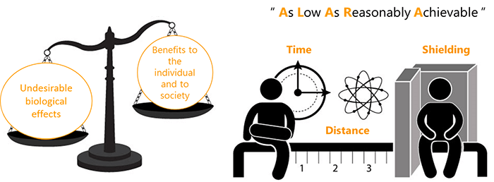
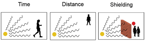
What are the 3 basic principles of ALARA? The basic concepts of ALARA are based on the principles of time, distance, and shielding, which are as follows:
- Minimizing the time spent in the radiation field. If you are in an area where radiation levels are elevated, complete your work as quickly as possible, and then leave the area. There is no reason to spend more time around it than necessary
- Maximizing the distance from a radiation source. Maximize your distance from a radioactive source as much as you can. This is an easy way to protect yourself because distance and dose are inversely related. If you increase your distance, you decrease your dose
- Using radiation shielding and other safety measures. To shield yourself from a radiation source, you need to put something between you and the radiation source. The most effective shielding will depend on what kind of radiation the source is emitting
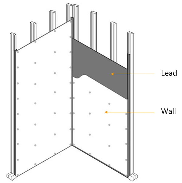
Lead-lining of the OR
Now that we know that shielding is an essential principle of radiation protection, let us describe the lead-lining process of the OR. Lead-lining the OR helps to reduce the amounts of radiation that spreads to the halls and the nearby rooms.
When it comes to the anti-radiation lining, each state has its own rules but the most standard Operating Rooms are lined in 0.5 mm of lead. During the planning stages of an OR room, a consulting qualified medical physicist has to assist to make sure that all regulatory guidelines are followed and proper radiation safety measures are applied.
Besides abiding by the principles of ALARA, there are many recommendations that aim to protect the operator as well as the patient from unnecessary radiation exposure in the OR. Let us take a look.
Safety Recommendations
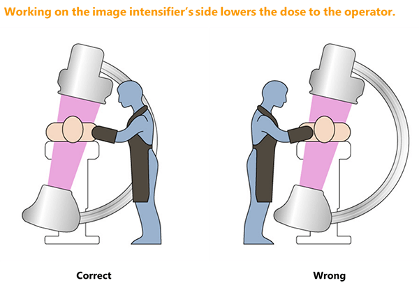
When the x-ray tube in a mobile C-arm unit is positioned under the patient and table, less radiation reaches the facial and neck region of the operator. It is recommended to keep the tube in this position when possible.
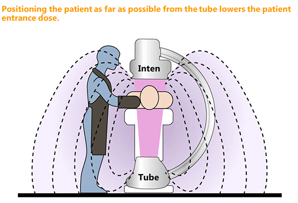
For mobile C-arm fluoroscopy units, the patient should be positioned as far from the x-ray tube as is practical, and as close to the image intensifier as possible, to minimize patient entrance dose.
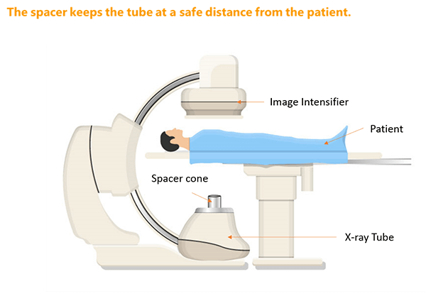
The use of the spacer is always recommended. The spacer is a safety device attached to the x-ray tube housing that keeps the patient from coming dangerously close to the x-ray source during a fluoroscopic procedure that uses a C-arm type of unit.
Placing the imaging source too close to the patient is a leading cause of skin injury from radiation exposure. The FDA requires fluoroscopic x-ray machines to maintain a minimum distance between the patient’s skin and the x-ray tube of 38 cm for fixed equipment and 30 cm for mobile ones.
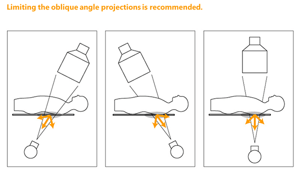
Higher exposure to the operator’s head and eyes results during oblique angle projections when the x-ray tube is tilted toward the operator. These projections should be utilized only when clinically or diagnostically required.
When possible, the operator should work on the image intensifier side of the table when oblique angles are applied.
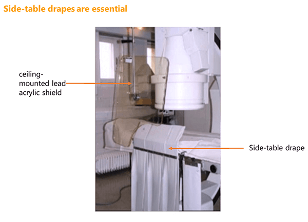
Most fluoroscopy systems contain side-table drapes or similar types of lead shielding. They should have at least a 0.25-mm lead equivalency and be placed between the patient and fluoroscopist. They can be configured on mobile imaging tables used with C-arms.
Recent advancements allow the combination of both the side-table lead drapes and the addition of a ceiling-mounted lead acrylic face and body shield. These drapes should be routinely inspected and replaced as needed. It is important that shielding does not interfere with the procedure and that the surgeon or interventional specialist is consulted prior to placement.
Recommendations specific to the Mobile Radiography in the OR Room
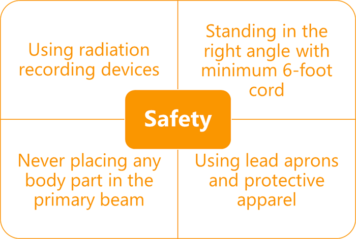
Let’s go deeper and describe the recommendations on how to use mobile radiography. Mobile radiography is one area in which the radiographer may receive a high exposure. The utilization of radiation recording devices is essential. Any dose that is received by any of the OR staff should be properly documented with personal dosimeters.
The radiographer should stand at a right angle to the tube and scattering object, with a minimum 6-foot cord for mobile radiography and strictly avoid placing any body part in the primary beam. There should be a stock of lead aprons and other protective apparel available in the OR for protection of operators, staff, and patients.
Now that we covered the general recommendations for radiation exposure safety in the OR, let us set a brief optimal technique to follow during the fluoroscopic studies.
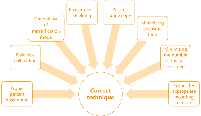
The correct technique when performing fluoroscopic studies in the OR includes proper patient positioning, field size collimation, minimal use of magnification mode, and proper use of shielding, pulsed fluoroscopy, minimizing exposure time and number of images recorded, and using the appropriate recording medium.
We will end this section by listing the proper technical parameters for fluoroscopic C-Arm use in the OR. It is important that both the proper technique as well as all the radiation safety measures be followed in the OR when utilizing fluoroscopy. This includes proper technical parameters:
- Pulsed fluoroscopy
- Reduced pulse widths and pulse rates
- Appropriate high voltage
- Beam current and pulse width product
- Appropriate beam filtration
- Increased source-to-skin distance
- Using the anti-scatter grid only when appropriate
- Proper field-of-view settings
- Collimation
- Proper use of last image hold
- Applying proper pre-image or post-image processing parameters
- Staff need to be aware of pain or tenderness of the skin; redness or any skin discoloration; rash, blisters, or peeling; appearance of sunburn; and hair loss in the affected area
Personal radiation measurement devices for OR staff
The Personal radiation measurement devices for OR staff include all of the following:
- Film Badge dosimeter
- Termoluminescent dosimeter (TLD)
- Optically Stimulated Luminescence dosimeter (OSL)
- Pocket dosimeter
What is the importance of the personal dosimeters? And how are they used?
The most common way to measure occupational exposure in the OR is to have all the staff wear personal dosimeters. In general, personal dosimeters are worn outside of the lead apron. Their use helps evaluate the effectiveness of prudent radiation protection practices.
Monthly reports received from dosimeter laboratories are official legal documents that are reviewed by the facilities’ radiation safety officer and/or consulting qualified medical radiation specialist. Attempts should be made to reduce any radiation exposure, no matter how small, as well as to put in place an action plan to minimize the dose or find the cause of the problem.
Now that we know why dosimeters should be used, let us describe their different types.
What is a Film Badge dosimeter?
The film badge dosimeter is a special radiation dosimetry film similar to a dental film enclosed in a plastic holder. It has metal filters along the open portion (aluminum, cadmium or copper). Each metal has a different atomic number to identify the type of the ionizing radiation.
When the film badge is exposed, deposits of silver atoms are distributed in the film emulsion that becomes dark upon development in proportion to the degree of radiation received. In high-dose areas like the OR, individuals may wear 2 film badges: one on the collar outside of the lead apron and one on the inside at chest or waist level. This dosimeter is not used anymore these days.
What is a Termoluminescent dosimeter?
This type is similar in appearance to film badges but uses a phosphor instead of the film. When exposed to radiation, a portion of the energy is stored in the crystal structure of the phosphor. TLDs are then exposed to heat and the absorbed energy is released as visible light. The amount of light is measured and a dose factor is calibrated. It is proportional to the amount of dose absorbed.
What is an Optically Stimulated Luminescence dosimeter?
With the Optically Stimulated Luminescence dosimeter, Aluminum oxide is utilized as the radiation detector. The exposure causes the electrons to go into an excited state. For processing, the aluminum oxide is exposed to a laser causing these electrons to go back to the ground state while emitting visible light. This light is then quantified to identify the type and amount of dose received.
What is a Pocket dosimeter?
A Pocket dosimeter has a special type of ionization chamber. It is used when there is a potential that an operator gets exposed to high amounts of radiation in a short time because it permits the operator to see the dose instantly. It is frequently used for interventional and cardiac procedures. It is used when there is a potential that an operator gets exposed to high amounts of radiation in a short time because it permits the operator to see the dose instantly. It is frequently used for interventional and cardiac procedures.
Radiation Protection Apparel and Barriers Used in the OR
This part covers the different apparel and barriers that can and should be used in the OR to ensure an optimal radiation protection for the staff, Lead and Non-lead Aprons, Thyroid Collars, Glasses, Upper Extremity, Hand, and Finger Protection, X-ray Attenuating Hand Cream, Secondary Barriers, Overhead Radiation Protection Suits, and Protective Disposable Sterile Leaded Drapes.
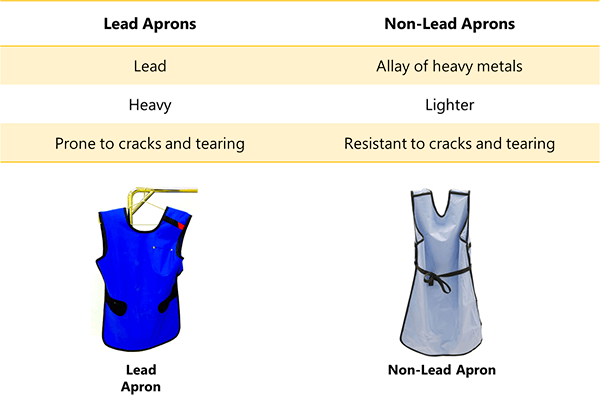
We will begin by the most basic radiation protection apparel, Lead and Non-Lead Aprons. Lead and Non-Lead Aprons are the mainstay of protection for operators during fluoroscopic procedures. They should be inspected and tested for attenuation effectiveness prior to being placed into service.
Lead has been the material of choice due to its high attenuation capabilities. The usual choice of lead apron thicknesses are 0.25 mm, 0.375 mm, and 0.5 mm depending on the procedures. The thicker the lead is, the heavier the Lead Apron becomes. Non-Lead aprons are lighter. They are composed of a heavy metals allay. They have the same attenuation coefficient of Lead but they are more resistant to cracks and tearing.
In addition to the aprons, the thyroid collars are equally essential.
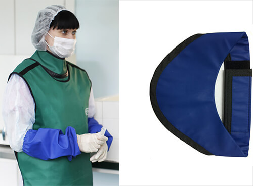
The thyroid is among the most susceptible sites to radiation-induced cancer. The American Thyroid Association states that an “increase in the use of diagnostic x-rays, necessitates the protection of the thyroid gland” in order to diminish thyroid cancer risk. It is especially important to take into account repeated exposure to radiation over one’s lifetime when assessing this risk, and physicians who are undertaking these procedures without adequate protection are at risk from scatter radiation. A thyroid collar reduces the amount of dose received by the thyroid.
Then comes the radiation protection glasses.
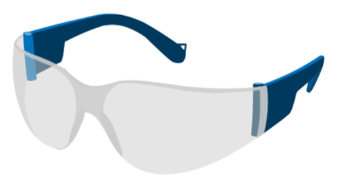
Eyes are sensitive to radiation and high doses received by the lens can cause cataract, vision troubles and blindness. Special glasses can help reduce the exposure of the eyes during fluoroscopic procedures.
Now let us move to the Upper Extremity, Hand, and Finger Protection. The physician’s hands are the most significantly exposed to radiation.
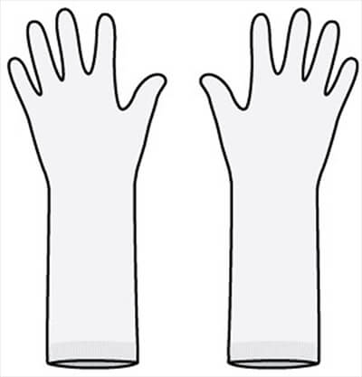
Radiation attenuating flexible gloves help minimize exposure to the operator’s hands while allowing him the dexterity to perform the procedure. Besides the gloves, a special X-ray attenuating cream provides extra protection for the operator’s hands.
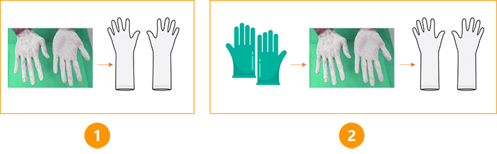
The use of a bismuth oxide-based attenuating hand cream during medical imaging procedures such as fluoroscopy may reduce the risk of exposing the operator’s hands to ionizing radiation. The cream is suggested to be used in two ways:
- Applied before the operator dons radiation attenuating gloves (extra layer of protection)
- It can also be applied directly to a gloved hand, followed by the application of a second glove
FDA warns that this cream is not intended for use “in or adjacent to the primary x-ray beam or the transmitted beam and should not be used in lieu of radiographic procedure gloves.”
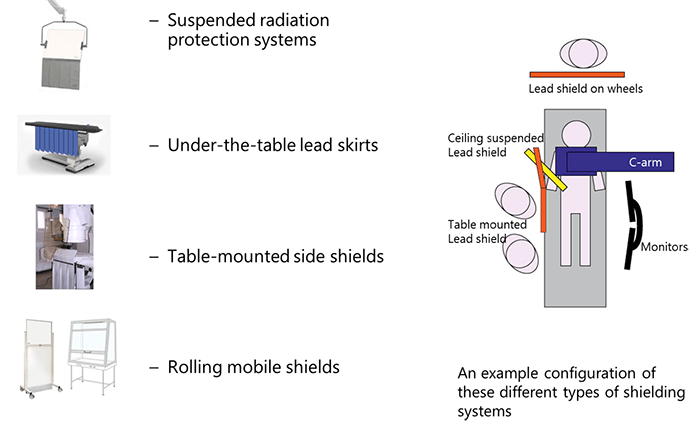
In addition to the radiation protection apparel, secondary barriers are mandatory in the OR. Secondary barriers can be equipment-mounted or mobile. Their purpose is to protect operators and other personnel from scatter radiation. They can be installed in different configurations and include:
- Suspended radiation protection systems
- Under-the-table lead skirts
- Table-mounted side shields
- Rolling mobile shields
It is important to note that the control booth area, which is the location of the operator who initiates the radiographic exposure, must be limited to a maximum amount of radiation not to exceed 1 mSv per week.
The secondary barriers at the control booth area must have 1/32 of an inch of lead equivalent filtration. Innovations in the radiation protection field lead to the apparition of new effective radiation protection apparel, such as the Overhead Radiation Protection Suits.
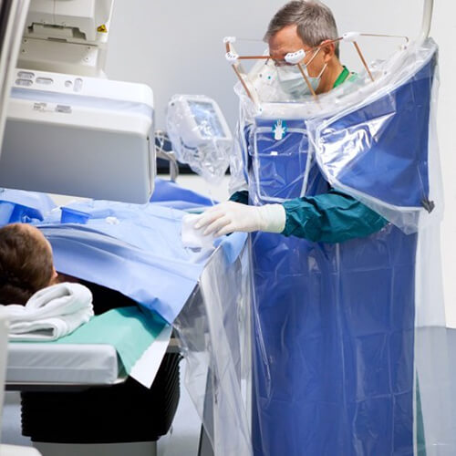
The main purpose of the Overhead Radiation Protection Suits is to provide protection against radiation to the operators during long procedures without weighing them down with the heavy leaded protective equipment.
They offer an overhead adjoining apparatus. The suit can move around thanks to its base and it can be mounted to the ceiling on rails also. This frees the operator’s shoulders and back from bearing the weight. They have many benefits:
- The thickness of the lead apron is 1 mm, which is twice the thickness of the usual standard for lead aprons
- They offer front and side protection
- The ceiling-suspended leaded shields reduce the lens dose rate due to the full coverage provided around the face region
Last but not least, come the Protective Disposable Sterile Leaded Drapes.
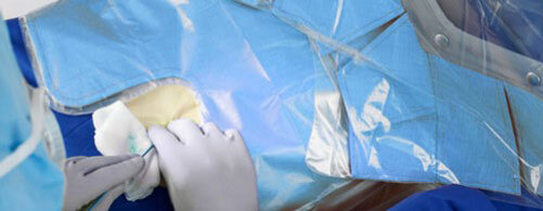
The Protective Disposable Sterile Leaded Drapes contain metallic elements such as bismuth or tungsten-antimony. Scatter reduction using these types of drapes is important to the lens of the eye of the operator who is constantly looking at the radiated region of interest.
Summary
To summarize the concepts of radiation protection in the Operating Room explained in this course, here are some general tips that guarantee an efficient protection against unnecessary radiation exposure:
- Always respect the 3 principles of distance, time and shielding
- Position the patient as far as possible from the tube
- Limit the oblique angle projections
- Work on the image intensifier’s side
- Use radiation recording devices
- Stand in the right angle with minimum 6-foot cord when using a mobile C-arm
- Never place any body part in the primary beam
- Use lead aprons and protective apparel
- Follow the correct technique for fluoroscopic procedures
- Use the proper technical parameters
Post-Test & CE Certificate:
Add to CartPrice: $6.00
| ✔ | Approved by the ASRT (American Society of Radiologic Technologists) for 1.5 Category A CE Credits |
| ✔ | License duration: 6 months from purchase date |
| ✔ | Meets the CE requirements of the following states: California, Texas, Florida, Kentucky, Massachusetts, and New Mexico |
| ✔ | Meets the ARRT® CE reporting requirements |
As per the ARRT regulations, you have up to 3 attempts to pass the Post-Test with a minimum score of 75%.
Upon the successful completion of the Post-Test (score 75% or more), you will need to fill up a 1 min survey and then you will be able to issue your CE Certificate immediately.
Refund Policy: Non-Refundable
