CT Image Quality and Informatics
Objectives:
- Define terminology reviewed in this course
- List the different types of resolutions
- Discuss factors affecting image quality in CT
- Understand the evolution of Informatics
- Explain the principle of networking
- Discuss Picture Archiving and Communication Systems
- Recognize the need for security and confidentiality
Description:
As a result of technological changes, image quality is another significant development in Computed Tomography. Early images appeared blocky but current images have shown much improvement. Those include improved spatial resolution, decreased scanning time, tube changes, and increased density resolution. Therefore, in this article, we will focus on how to improve the image quality in computed tomography then we will show the importance of informatics in improving the human health and the delivery of health care services. This article is accredited by the ASRT for 1.25 Category A CE Credits.
List of Factors
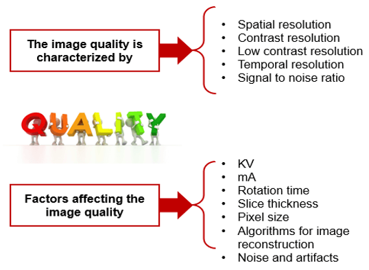
Essentially there are three main parameters, spatial resolution, contrast resolution and noise with many factors impacting quality.
We MUST explain the procedure and answer any questions. Be sure and address any concerns they may have about pain. This will help to ensure the examination goes smoothly. And always remember to monitor your patient during the entire study.
Spatial Resolution
Many factors can impact image quality. Technical factors such as kVp and mA, slice thickness and rotation time, the pixel size and algorithms for the reconstruction and finally noise and artifacts.
It provides clear images of small structures with variable sharpness of contrast. Parameters that affect spatial resolution:
- Slice thickness
- SFOV size
- The matrix size
- Focal spot size
- Number of detectors
- Algorithm
- Pre-patient collimator
Spatial resolution describes the amount of blurring in an image. Contrast resolution is the ability to differentiate small differences in density within the image. Spatial resolution in CT is the ability to distinguish between objects or structures that differ in density. A high spatial resolution is important for one to discriminate between structures that are located within small proximity to each other.
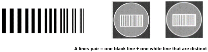
The number of line pairs per unit length is called the spatial frequency. Large objects have a low spatial frequency while small objects have a high spatial frequency.
- Standard resolution: 12 lines pairs/cm
- High resolution: 15 pl/cm
- Very high resolution: 30 pl/cm
SR and SFOV Size
The field of view (FOV) plays an important role in spatial resolution. As the FOV increases so do the pixel size resulting in a decrease in the spatial resolution.
Reducing the “targeted” or “reconstructed” FOV reduces the possibility of different tissues occupying the same pixel.
Minimizing the noise with a large reconstructed FOV is attained only by compromising the image’s spatial resolution.
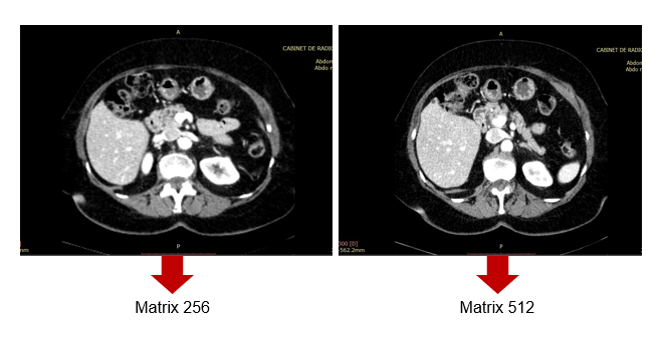
SR and Matrix Size
As for matrix size, 512-by-512 has been used in conventional CT, but larger matrix sizes, such as 1024-by-1024 and 2048-by-2048, are available with Ultra high-resolution CT (U-HRCT).
According to a new study recently published in Academic Radiology, in ultra-high-resolution computed tomography (U-HRCT) scans, a large matrix size maintains the spatial resolution and improves the image quality and assessment of lung diseases when compared to a 512-matrix size.
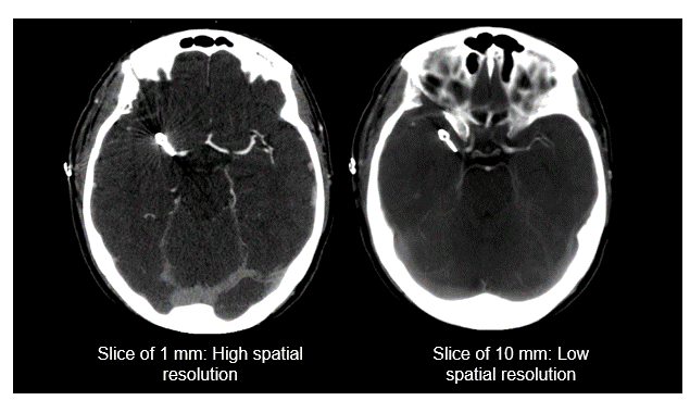
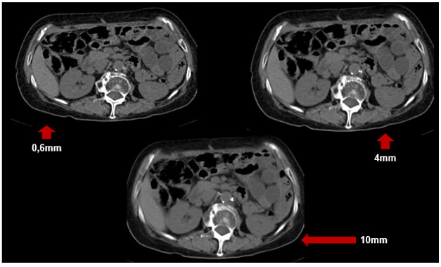
SR and Slice Thickness
Remember, a high spatial resolution is important for one to discriminate between structures that are located within proximity to each other.
The thickness of the slice also impacts spatial resolution. As shown in these two images, when the slice thickness is larger the spatial resolution is lower. The thicker the slices the less the detail in the image. Large slice thicknesses reduce spatial resolution in the cranial-caudal axis; they also reduce the sharpness of edges of structures in the transaxial image.
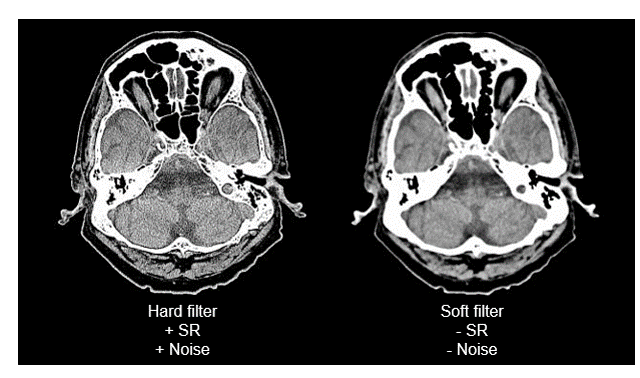
SR and Hard Filter
The harder the filter, the spatial resolution increases and the more the noise in the image increases.
Contrast Resolution
Contrast resolution allows the differentiation of small structures depending on their densities.
Contrast resolution is measured in line pairs per centimeters. It is how it differentiates between two objects. There is high-contrast resolution, cross-plane resolution, and low contrast resolution.
Low contrast objects may require a larger pixel size so that the detectors can provide sufficient data for a visible difference but the total resolution is reduced.
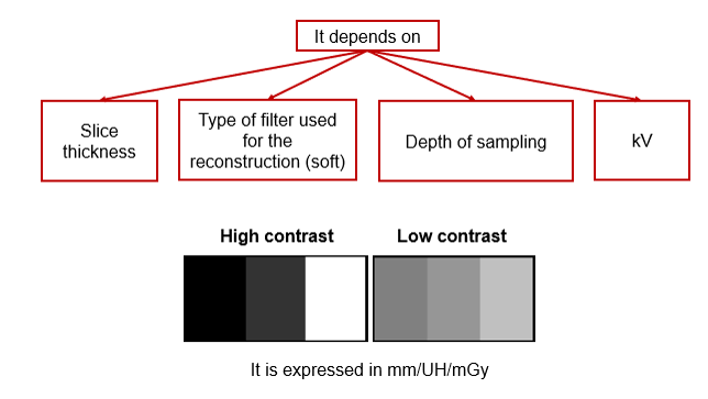
The choice of x-ray tube voltage affects the image contrast. Low kV values mean higher contrast or few shades of gray, more black and white, while high kV values are selected when acquiring images with low contrast or one that requires seeing many shades of gray.
Higher kVp means that the photons have higher energies and can penetrate thicker objects.
This image shows the effect of the kVp on image contrast. Note the differences between 100 and 120 kVP. The higher the kVp, the lower the contrast, known as low contrast resolution.
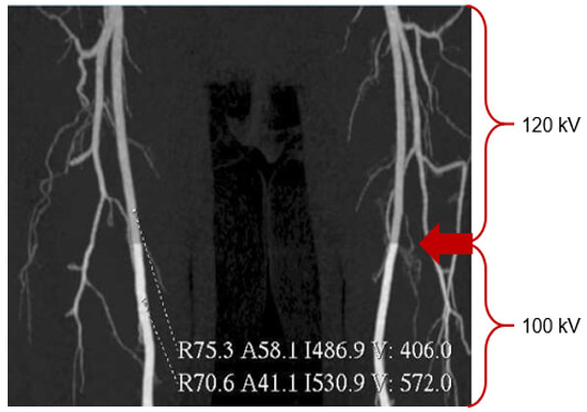
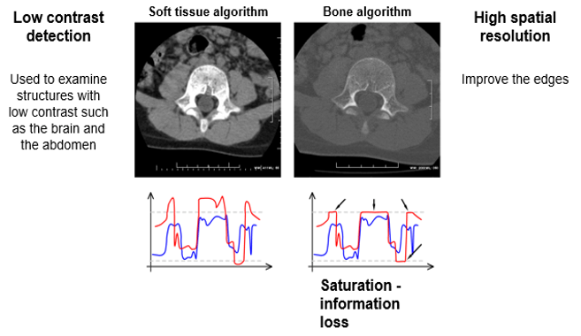
Low contrast detection is used to examine structures with low contrast such as the brain or the abdomen. This is accomplished by using higher kVp.
CR and Slice Thickness
These images demonstrate that the thicker the slice, the lower the contrast resolution. Although in general, an image with a thicker slice contains more x-ray photons (or less noise), the partial volume effect can reduce the visibility of smaller objects.
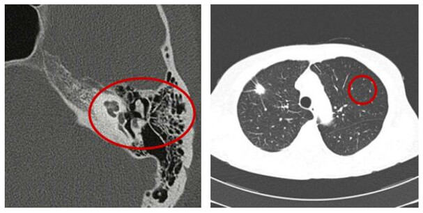
Spatial Resolution / Contrast
In areas such as the inner ear and the thorax, there are large differences in densities between very close structures. Using a wide window, there will be little visible noise in the image. Thus, the delivered dose could be low.
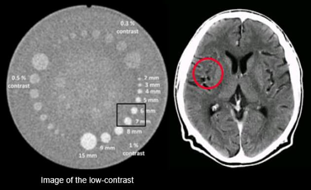
Low Contrast Resolution
The ability to distinguish between tissues with slight contrast differences is known as low contrast resolution. This is one of the advantages of CT and conventional radiography.
Temporal Resolution
Temporal resolution is an indication of a CT system’s ability to freeze motions of the scanned object. Several factors influence the temporal resolution. The key factors are the gantry rotation time, acquisition mode, type of image reconstruction, and the pitch.
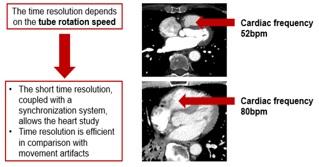
The concept of temporal resolution is fundamental to cardiac CT and MRI, in which a rapidly beating heart is imaged over the order of milliseconds into multiple frame-captures. The most straightforward way to reduce or eliminate the motion impact is to increase the scan speed.
In reality, excellent temporal resolution can be achieved through many patient-centric techniques. These techniques rely on the sophisticated acquisition and image reconstruction software and not solely on the mechanics of the scanner itself.
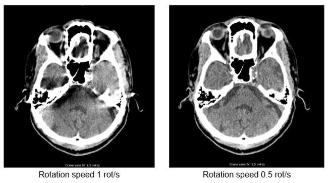
- The rotation speed is the time in seconds required for the tube to achieve 1 complete rotation (360°) and acquire its raw data
- Used for the skull and the lumbar spine. It is avoided for thorax-abdomen and heart scanner exams requiring long time apnea
- To avoid image degradation caused by the patient movements (artifacts) and involuntary movements (peristalsis and heartbeats)
Signal to Noise Ratio
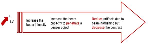
kVp
Increasing the kVp will improve the signal to noise ratio. This increase in beam intensity allows for better penetration of denser objects.
Sufficient high technique is necessary for contrast resolution of soft tissue in the brain and also of large patients who are being scanned for their spine. Reduce artifacts due to beam hardening but decrease the contrast.
mA
The signal-to-noise ratio in CT roughly follows the same principles as those of plain radiographs. It is calculated by comparing the level of the desired signal to the background deviation from normal pixel values. In general, the larger the number of photons transmitted, the greater the SNR.
In CT, the signal-to-noise ratio is determined by mAs-the greater mAs increases the SNR.
Remember, a lower signal-to-noise ratio generally results in a grainy appearance to images. AN underexposed CT image presents a noisy appearance due to the insufficient number of photons reaching the detectors.
Noise is a set of incoherent signals that degrade the images. Noise in CT is an unwanted change in pixel values in an otherwise homogenous image.
Noise in CT is measured via the signal to noise ratio (SNR) by comparing the level of the desired signal (photons) to the level of background noise (pixels deviating from normal). CT images have been reconstructed from raw data using filtered back projection (FBP) since the inception of the modality.
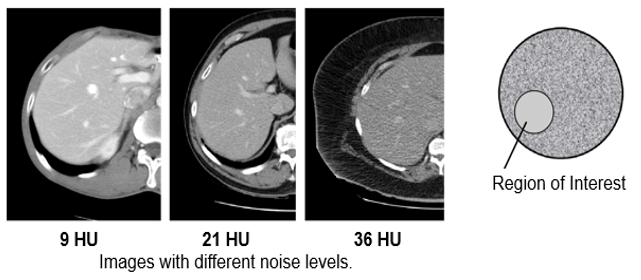
Standard Deviation SD
The standard deviation is the deviation of CT numbers (Hounsfield Units) in the region of interest. The acceptable limits for the CT Number Standard Deviation Test should be the Standard Deviation of water not exceeding a level specified by the manufacturer.
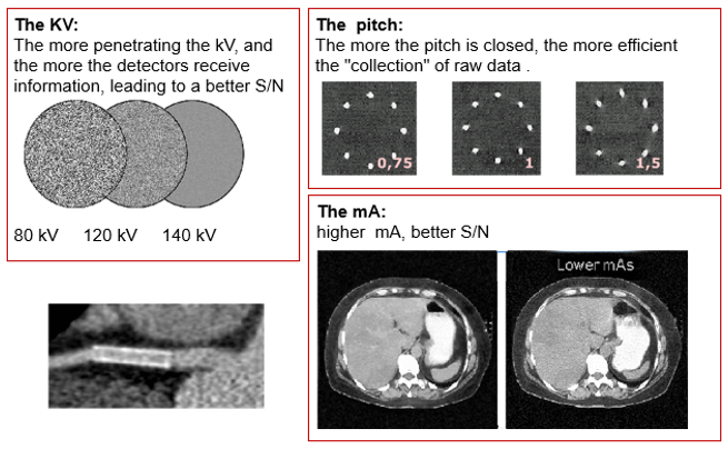
Improvement of S/N
The improvement of the signal to noise ratio can be accomplished in the following manner: the more penetrating the kV, and the more detectors receiving information; the higher the mA, the better the signal to noise ratio, and the more the pitch is “closed” the more efficient the collection of raw data.
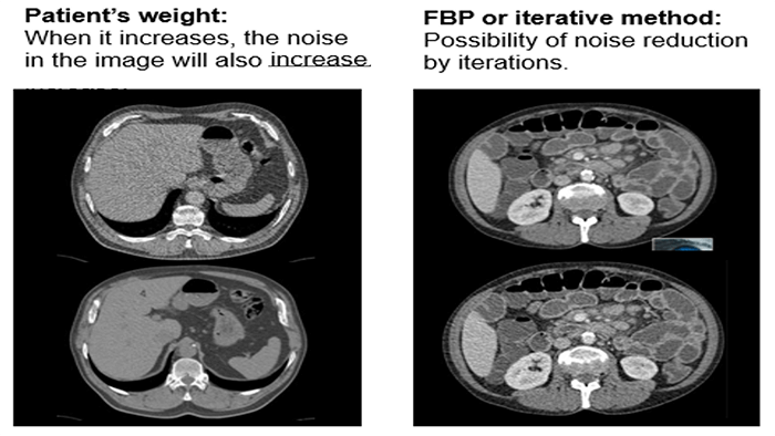
When the patient’s weight increases the noise in the image will also increase. Increasing the kVp or mA will not improve the noise.
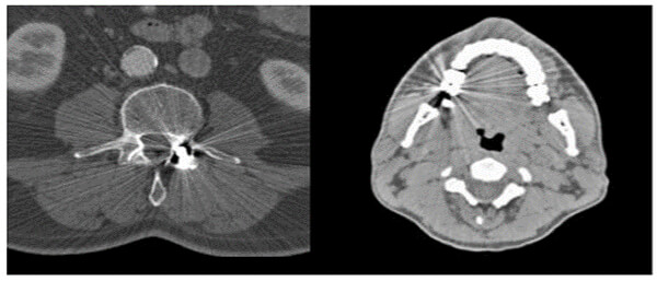
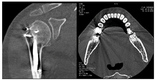
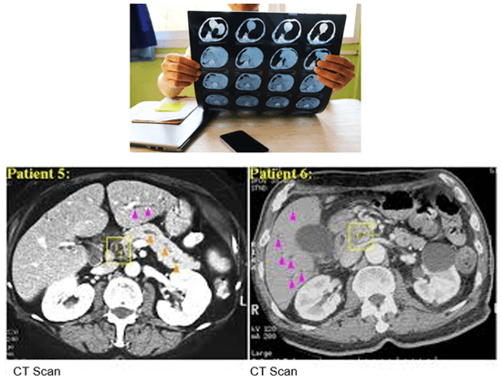
Metal implants such as shrapnel, surgical clips, pacers, joint prostheses, wires, pedicle screw placement, stenting, usually undergo follow-up CT imaging. These metallic implants lead to severe streak and shadow artifacts in CT images that superimpose the structures of interest and deteriorate image quality. This is because metallic objects are a high-density material, which is strongly scattered to the transmitted x-ray beam during CT examination.
Various metal artifact reduction techniques have been developed to reduce metal artifacts, and the most commonly used reconstruction algorithm for CT has filtered back projection (FBP), interpolation methods, and iterative reconstruction methods.
Signal to Noise Ratio and Dose
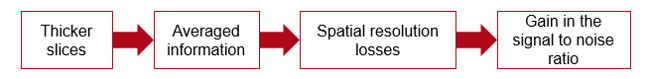
When the slices are thicker, the information is averaged. We then lose spatial resolution but gain in the signal to noise ratio.
Iterative reconstruction and denoising techniques facilitate CT radiation dose reduction because they reduce image noise, which is one of the limiting factors of dose reduction.
Contrast / Noise
Contrast-to-noise ratio (CNR) is a measure used to determine image quality. The contrast to noise ratio is defined as the difference in signal contributions between different tissues divided by the background noise. As noise increases in an image, contrast resolution decreases.
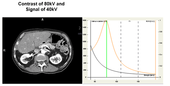
The integrated concept with the introduction of dual-energy acquisition.
It’s the contrast/noise ratio in the image with iodine contrast injection. In general, the best value is obtained for the image energy of 70KeV.
Origins of Artifacts
Artifacts are commonly encountered in clinical CT and can obscure an area of pathology making it impossible for a radiologist to visualize.
There are many different types of CT artifacts including noise, beam hardening, scatter motion, helical, cone-beam and metal artifacts.
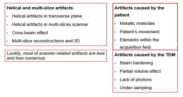
Equipment Related Artifacts
The formation of these artifacts is due to the impossibility of algorithms to take into consideration the very high-density values. This causes misinterpretation of images as the metals absorb more of the x-rays. This absorption creates shadows.
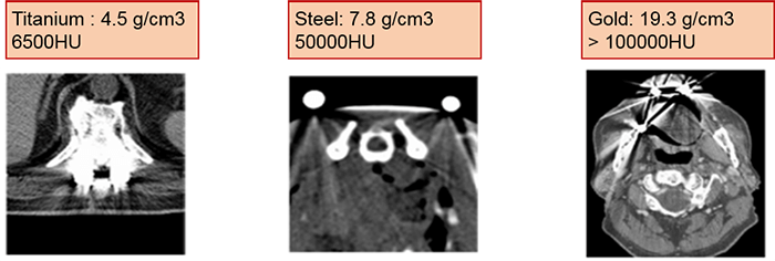
Compare the density of the prosthetic materials in these images all taken at 120 kV. As you can see, gold has the highest Hounsfield units.
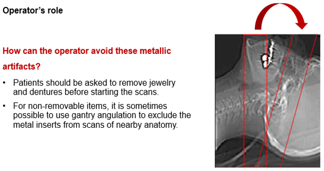
As part of an operator’s role, patients should be asked to remove jewelry and dentures before starting the scans. This assists in avoiding some metallic related artifacts.
For non-removable items such as dental fillings and joint prosthesis, it is sometimes possible to use gantry angulation to exclude the metal inserts from scans of nearby anatomy.
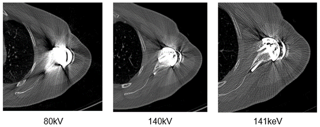
It is also possible to adapt the kV values used based on the visualized structure or to use dual-energy protocols. Notice the difference in streaking in these three images.
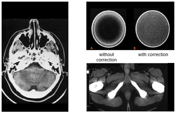
Streaking caused by over ranging can be greatly reduced using special software corrections. Manufacturers use a variety of interpolation techniques designed to substitute the over ranged values in attenuations’ profile.
However, there is always a detail loss around the metal/tissue interface, which is often the area of interest in diagnosis.
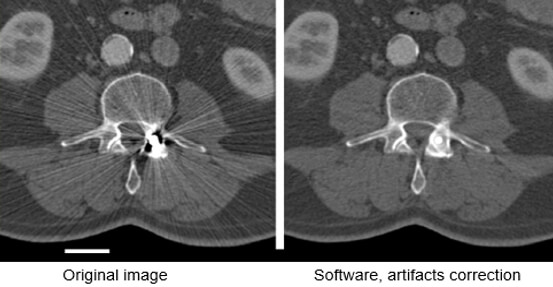
This image shows the effectiveness of metal reduction artifact software. Notice how much better the resolution is in the image on the right.
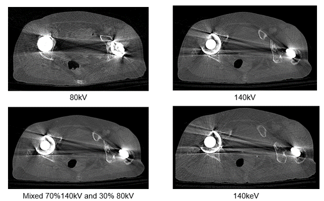
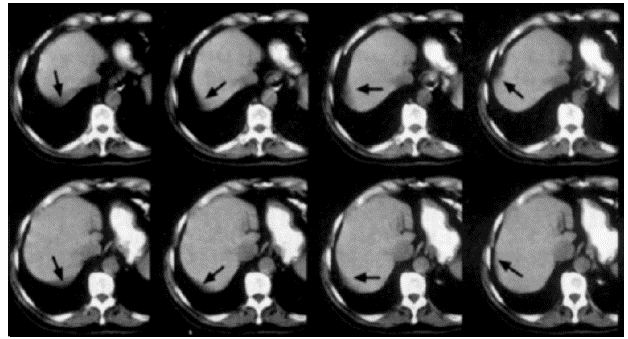
Let’s look at the differences in these four images taken at different dual energy levels. Compare the streak artifacts with the 80kV, 140 kV, the mixed acquisition of 140kV and 80 kV and the last at 140 keV.
Motion Artifacts
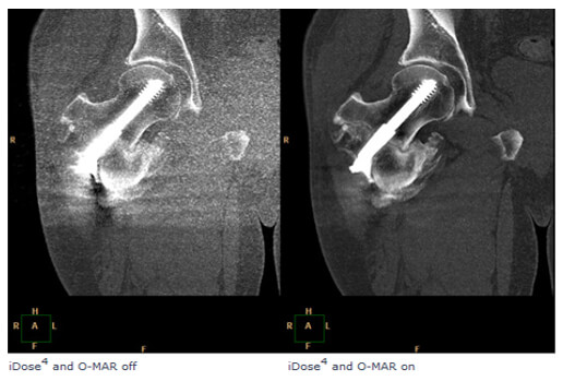
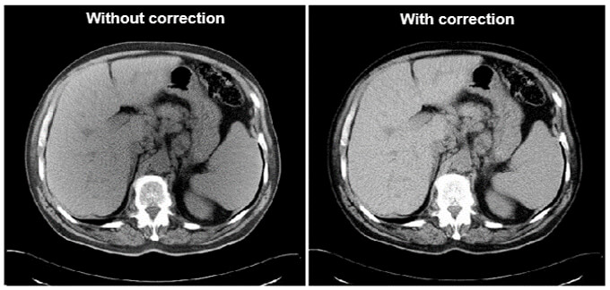
Motion artifacts are caused by the patient or tissue movement such as breathing or peristalsis. These types of artifacts have been greatly improved because of the speed in multi-slice scanning used today.
Faster scanners have improved motion as the patient has less time to move during the scan. This can be accomplished with faster gantry rotation or more x-ray sources. Compare these two images for motion. The image on the right has a much better resolution than the one on the left.
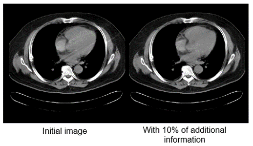
Motion artifacts can be reduced by using special reconstruction techniques. 10% is added to the 360-degree standard rotation. Repeated projections are averaged which reduces motion artifacts. The image on the left shows less motion when this technique is used.
Exterior Elements
Exterior materials such as ECG leads, O2 tubes or limbs can cause artifacts. The technologist should put the patient in the correct position and then move them out of the way possible.
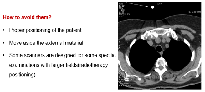
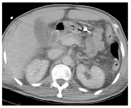
For example, arms along the side of the patient’s body can cause an undesirable artifact. Notice the streaking in this image.
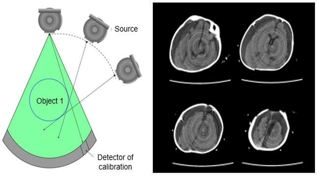
Ring Artifacts
If one of the detectors is out of calibration on a scanner, the detector will give a consistently erroneous reading at each angular position, resulting in a circular artifact.
A scanner with solid-state detectors, where all the detectors are separate entities, is in principle more susceptible to ring artifacts than a scanner with gas detectors, in which the detector array consists of a single xenon-filled chamber subdivided by electrodes.
The presence of circular artifacts in an image is an indication that the detector gain needs recalibration or may need repair services.
Beam Hardening Artifact
Beam hardening produces dark streaks between two high attenuation objects with surrounding bright streaks. These can be reduced by using a higher beam.
Artifacts which result from lower energy photons being absorbed, high-intensity photons are left to strike detectors.
Scanning at a higher kVp will result in a harder x-ray beam and less beam hardening artifacts.
Helical Artifact
Helical artifacts can sometimes be seen with faster scanning techniques. In general, the same artifacts are seen in helical scanning as in sequential scanning. However, there are additional artifacts that can occur in helical scanning due to the helical interpolation and reconstruction process. The artifacts occur when anatomic structures change rapidly in the z-direction (ie, at the top of the skull) and are worse for higher pitches. Helical and multisection technique artifacts are produced by the image reconstruction process.
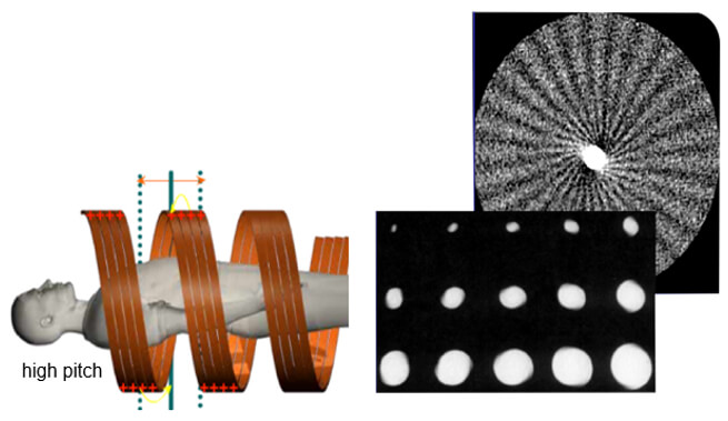
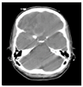
This set of artifacts shows a fast anatomical variation in the Z direction.
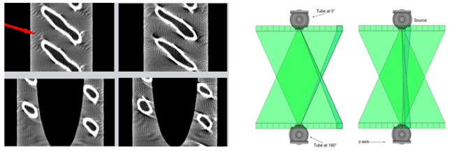
Cone-Beam Artifact
When the collimation is greater than the Z-axis, the detectors will receive less information. This distorts the image during the tube rotation. When mathematical algorithms are used the artifact can be corrected. High collimation highlights the cone-beam artifacts.
Terminology
We should consider the many ways that technology and data have made an impact on health and healthcare around the globe. While there is still so much work to do to make technology in healthcare the seamless system we desire, but we can reflect on how far we have come.
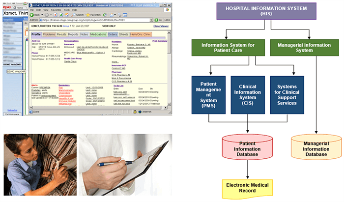
It is important to recognize the acronyms for terminology used when discussing Informatics. Biomedical Informatics (BMI) refers to platforms that are used for medical purposes such as patient care. A picture archiving and communication system (PACS) denotes a BMI platform which is configured in a manner that facilitates storing, retrieving, and distributing medical images.
A hospital information system (HIS) and a radiology information system (RIS) encompass BMI platforms used in a health-care facility and a radiology department. And finally, Electronic Medical Record (EMR) otherwise known as Electronic Health-care record (EHR) are electronic versions of a patient’s collection of medical documents.
Evolution of Health Informatics
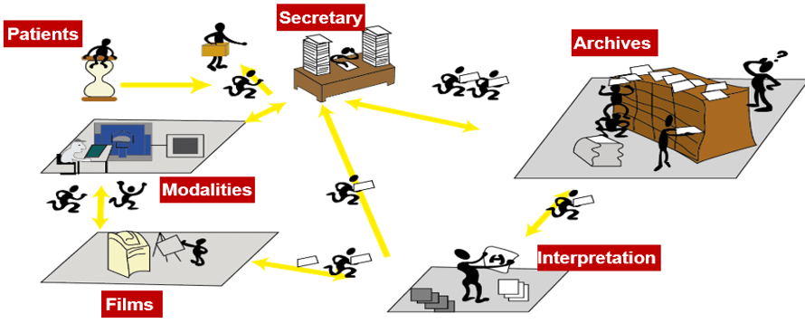
In the years before 2008, most departments in the country used the same charting system. It was a system of charts, forms, and cubbies. The charts were moved from one cubbie to the next, from the nurses and doctors to the medical secretaries.
The daily struggle in imaging was to find your patient’s previous reports or films, review any information that had been updated on the patient in their chart and prepare images for the radiologist to compare. More time was spent finding the previous images than caring for patients. We have now progressed to electronic records making the lives of all health care professionals much easier. This has made a huge impact on medical imaging.
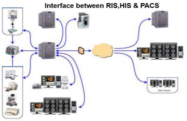
The work organization before the RIS- PACS integration:
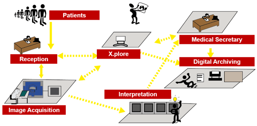
Here we can see the work organization after the RIS-PACS integration. In fact, PACS is used by radiology personnel to manage the workflow of patient exams:
Operation
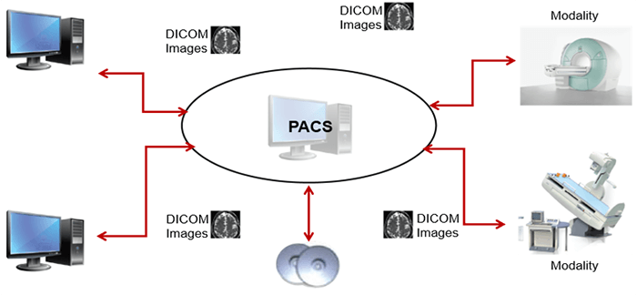
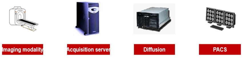
This simplified diagram indicates the image data flow between the imaging modality and PACS.
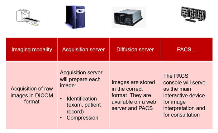
PACS is usually an integration of input from digital devices which may be any radiological modality. These devices include Image acquisition device, image storage server for short or long term storage of data, transmission network, display station, imaging work station, and user interface, camera to convert to hard copies images on a need basis, and integration to radiology information system and hospital information system.
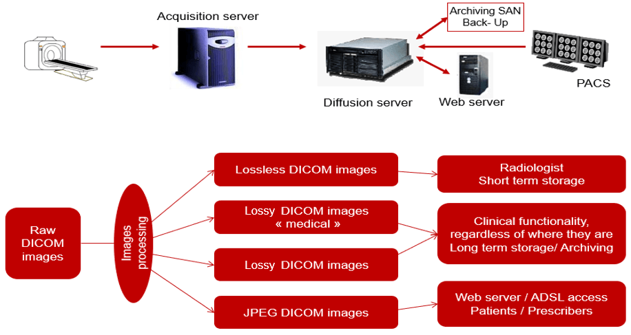
Acquisition
This simplified diagram indicates the image data flow between the imaging modality and PACS.
- Flow: Modalities -> PACS
The flow of “raw” format images. Acquisition protocol for each modality (automation and technologist dependent).
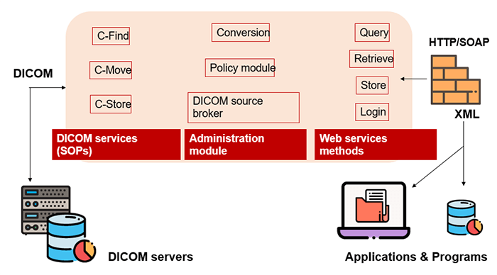
DICOM
DICOM is the international standard used to transmit, store, retrieve, print, process, and display medical imaging information. It involves the integration of image-acquisition devices, PACS, workstations, VNAs and printers from different manufacturers. DICOM is an acronym for Digital Imaging and Communications in Medicine and originated in 1983. It was developed and is maintained to meet the evolving technologies and needs of medical imaging today. It is free to download and use by institutions.
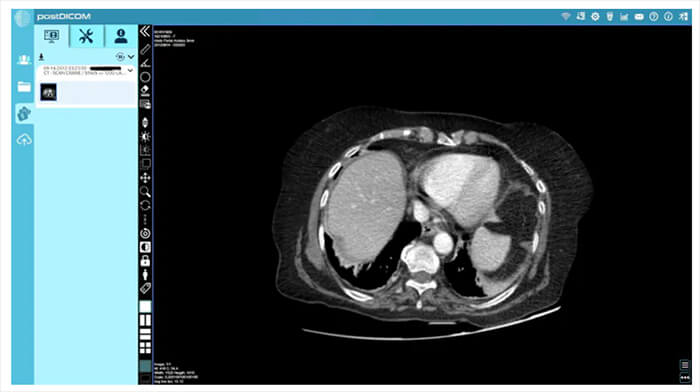
Post DICOM image
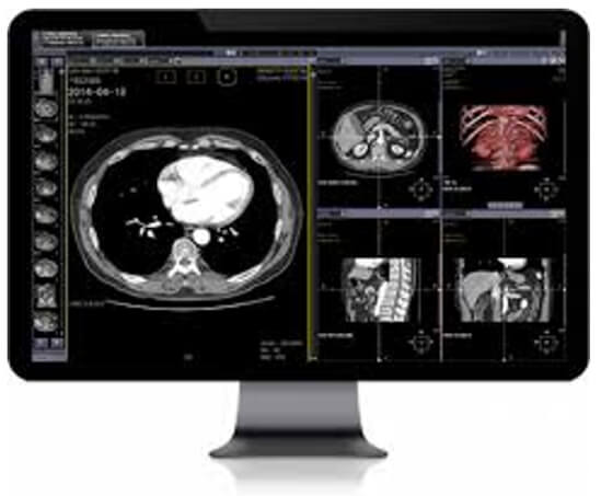
To view these images on your computer, you will have to use a DICOM viewer, which will interpret the file information and display it as an image. There are many different viewers available. One such viewer, Post DICOM, is an online radiology/ DICOM-sharing service. It provides a cloud with 50GB of free space for uploading, organizing and sharing DICOM files, and it comes with a powerful DICOM viewer. It allows you to organize your files as well as search cases by patient name, patient ID or case number.
Hard Copy Display
Images that are visualized on film are referred to as hard-copy displayed. These are usually produced with a laser printer or a dry processor. Dry processors do not use a developer, fixer or a wash bath to process the image. Very rarely are digital images produced on film nowadays.
Soft Copy Display
Today, in most filmless environments, images are viewed on a flat-screen monitor, known as a soft copy. LED monitors, or light-emitting diodes, use small efficient lights and are the most common.

PACS
A picture archiving and communication system (PACS) is a medical imaging technology that provides economical storage and convenient access to images from multiple modalities. The universal format for PACS image storage and transfer is DICOM (Digital Imaging and Communications in Medicine). Combined with available and emerging web technology, PACS can deliver timely and efficient access to images, interpretations, and related data. PACS is used by radiology personnel to manage the workflow of patient exams.
Electronic Medical Records
Electronic medical records (EMRs) are digital versions of the paper charts in clinician offices, clinics, and hospitals. EMRs contain notes and information collected by and used by clinicians in that office, clinic, or hospital. They are an electronic (digital) collection of medical information about a person that is stored on a computer. An EMR includes information about a patient’s health history, such as diagnoses, medicines, tests, allergies, immunizations, and treatment plans. They are mostly used by providers for diagnosis and treatment.
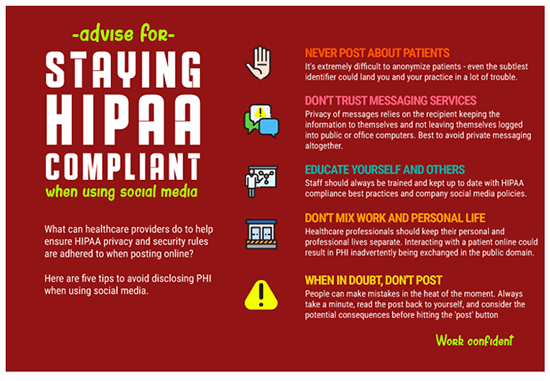
Security and Confidentiality
The NCCoE released a draft of the NIST Cybersecurity Practice Guide, SP 1800-24, Securing Picture Archiving and Communication System, on September 16, 2019. PACS is nearly ubiquitous in hospitals, prompting the Healthcare Sector to identify its security as a critical need. HDOs face many challenges in securing a PACS.
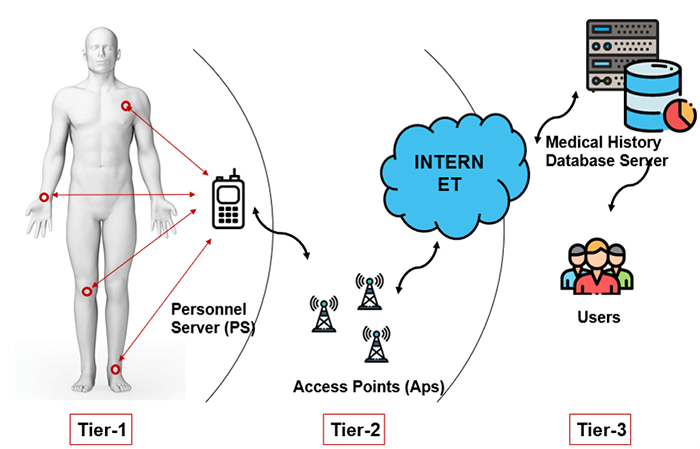
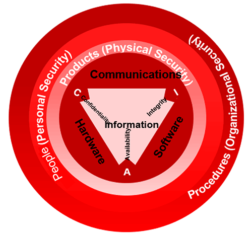
PACS requires controls that provide significant integrity, availability, and confidentiality assurances since it ties into doctor-patient workflow management. The results are based on image interpretation which aids in deciding a patient’s next step. These include the determination of health condition, follow-up visits, patient care, and other health-related actions. The three main tiers for possible confidentiality violations are Personnel servers, access points, and end-users.
Malware
PACS may have vulnerabilities that, given its central nature, may impact an institution’s ability to render patient care or to preserve patient privacy. These vulnerabilities could impede the timely diagnosis and treatment of patients if medical images are altered or misdirected. These vulnerabilities could also expose an institution to risks of significant data loss, malware and ransomware attacks, and unauthorized access to other parts of an institution enterprise network.
Confidentiality
Justice Samuel Dennis Warren and Justice Louis Brandeis define privacy as the right “to be let alone”. Information of a patient should be released to others only with the patient’s permission or allowed by law. When a patient is unable to do so because of age, mental incapacity the decisions about information sharing should be made by the legal representative or legal guardian of the patient. Information shared as a result of clinical interaction is considered confidential and must be protected.
The key to preserving confidentiality is to allow only authorized individuals to have access to information. This begins with authorizing users based on pre-established role-based privileges. The administrator identifies the user, determines the level of information be shared and assigns usernames and passwords. The user should be aware that they will be accountable for the use and misuse of the information they view and only have access to the information they need to carry out their responsibilities. Hence assigning user privileges is a major aspect of medical record security. Always remember HIPAA as you were taught in your radiography program.
Security Breach
Security breaches threaten patient privacy when confidential health information is made available to others without the individual’s consent or authorization. Keeping records secure is a challenge that doctors, public health officials, and federal regulators are just beginning to understand. Cloud storage, password protection, and encryption are all measures health care providers can take to make portable EHRs more secure.
Security Measures
Security measures such as firewalls, antivirus software, and intrusion detection software must be included to protect data integrity. Specific policies and procedures serve to maintain patient privacy and confidentiality. For example, employees must not share their ID with anyone, always log off when leaving a terminal and use their own ID to access patient digital records. A security officer must be designated by the organization to work with a team of health IT experts.
Networking
Networks, also known as servers or gateways or cloud computing, are not visible like hardware or software components but are a critical component of informatics. These are the links to sharing data and information and are the foundations of the growth of informatics in the health care arena today. A telecommunication or computer network uses a data link to share information.
Local area networks (LAN) or wide area networks (WAN) are the most common networks utilized today.

Networking allows an increase in the accuracy of clinical information as well as a faster turnaround of results. Computer networks are controlled by switches, commonly referred to as hubs, bridges or routers. Internet-based computing, or cloud computing, allows for virtual access to shared resources. A large reliable, high-speed bandwidth is required to move image data from one place to another.
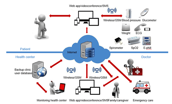
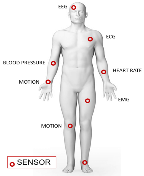
Wireless Body Area Network (WBAN)
Wireless Body Area Network (WBAN) is a technique used for remotely monitoring the patient’s health and gathering the related information from the embodied sensors. It consists of a small wireless network that contains several small devices, i.e. sensor nodes and actuators. The sensor nodes are placed directly either on the body or under the skin of a person to compute certain body parameters such as an electrocardiogram (ECG), electroencephalogram (EEG), body movement, temperature, blood pressure, blood glucose, and respirations.
PDA
A smartphone can remotely access the information sensed by the sensors or a Personal Digital Assistant (PDA) between the patient and a doctor, nurses, pharmacies who take sensitive decisions or actions depending on the information acquired from those sensors. These critical decisions and medical information must be protected against unauthorized access that could be dangerous to the life of the patient and sometimes lead to death, i.e. change of dosage of drugs or treatment procedures, if falls on the wrong hand. Thus, scalable and strict security mechanisms are mandatory and should include secure group management, confidentiality, privacy, integrity, authorization, and authentication.
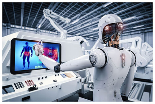
Artificial Intelligence (AI)
One of the most promising areas of health innovation is the application of artificial intelligence (AI) in medical imaging, including, but not limited to, image processing and interpretation. Indeed, AI may find multiple applications, from image acquisition and processing to aided reporting, follow-up planning, data storage, data mining, and many others. Due to this wide range of applications, AI is expected to massively impact the radiologist’s daily life.
Post-Test & CE Certificate:
Add to CartPrice: $5.00
| ✔ | Approved by the ASRT (American Society of Radiologic Technologists) for 1.25 Category A CE Credits |
| ✔ | License duration: 6 months from purchase date |
| ✔ | Meets the CE requirements of the following states: California, Texas, Florida, Kentucky, Massachusetts, and New Mexico |
| ✔ | Meets the ARRT® CE reporting requirements |
As per the ARRT regulations, you have up to 3 attempts to pass the Post-Test with a minimum score of 75%.
Upon the successful completion of the Post-Test (score 75% or more), you will need to fill up a 1 min survey and then you will be able to issue your CE Certificate immediately.
Refund Policy: Non-Refundable
