
Introduction to MRI
Objectives:
- Define the MRI
- List the key components needed to create an MRI image
- Provide a brief explanation of how hydrogen protons are used in MRI
- Define a magnetic field and explain how a magnetic field is created
- Explain the difference between homogeneity and inhomogeneity
- List the three types of magnets used in MRI imaging and provide a list of the advantages and disadvantages of each
- Identify types of energy on the electromagnetic spectrum
- Define radiofrequency and explain how it is used in MRI
- Explain magnetic pull
- List several examples of ferrous materials
- List dangers associated with magnets and radio frequencies in MRI
- List the dangers of the strong magnetic field
- Explain how energy is transferred to the patient during an MRI scan
- List essential screening questions all patients must answer
- List the four zones of MRI and give an example for each zone
- Define GFR and explain the importance related to MRI contrast
- List the basic types of MRI contrasts
- Select contraindications to MRI scans from a list
- Explain normal vital sign ranges for adult patients
- Explain RF burns and provide examples of causes of burns
- List pharmaceuticals used in MRI to provide relaxation to claustrophobic patients
Description:
The purpose of this article is to introduce users to MRI, how it works, how magnetic fields work, why safety is a concern around an MRI unit, and prepare users to explore the concept of MRI more deeply. Then, we will learn about patient care and safety in the MRI environment: We will discuss the transfer of energy during RF transmission, as well as dangers presented which can cause RF burns. And we will discuss the difference between MRI safe, MRI conditional and MRI contraindicated affect us at work. This article is accredited by the ASRT for 2.5 Category A CE Credits.
In order to understand how MRI works, we must first understand what MRI is and how it came to be. We will then move on to the general principles of how MRI works. We will also discuss how the molecular structure of the human body provides us with part of the tools essential to creating an MRI Image.
MRI stands for Magnetic Resonance Imaging. In its early days, MRI was referred to as NMR, Nuclear Magnetic Resonance, because of its dependence on the nuclear structures of an atom. Many confused this with a negative connotation associated with the word Nuclear, so that word was dropped. As we will learn later, MRI does not use ionizing radiation at all in the collection of data and creation of an image. MRI does use radiation, in the form of radiofrequencies, but it is not ionizing, which means it cannot cause cellular damage like x-rays and radionuclides.

The imaging in MRI involves the very small magnetic force created by spinning protons within the nucleus of atoms. Protons are dipoles, much like the earth, with a north and South Pole and they spin or rotate on an axis. All dipoles process, or spin, at a unique frequency. This means that every proton has its own frequency at which it spins. This basic knowledge led to quite a realization about magnetic fields and signal given off by these magnetic fields under certain conditions, which we will learn more about as we progress. For now, it’s sufficient to say that this is the basis for what we know about MRI and how it works.
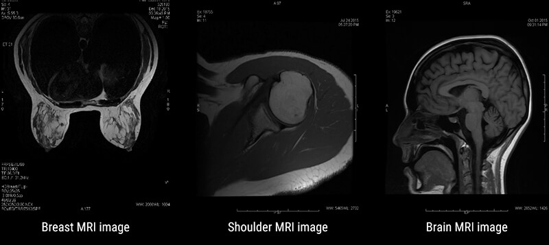
MRI has many applications in medical imaging. It is best known for its superb spatial resolution or the ability to resolve fine detail and small objects. Some of the most common applications are: Musculoskeletal or MSK, Neurological studies, functional studies, liver imaging, breast imaging and even cardiac imaging.
In MSK work, MRI is useful for looking at joints, tendons, muscles, bones, and vascular structures. Neurological imaging allows us to follow Multiple sclerosis progression and even allows for determining active lesions vs. chronic lesions. And breast imaging is a way to look closer at breasts without the use of ionizing radiation. These are just a few examples of the multitude of uses of MRI.
As with any imaging test or procedure, MRI is not without disadvantages, but the advantages of MRI far outweigh them. Advantages of MRI include superb detail, or spatial resolution. MRI also allows us to evaluate the tissue in question from various angles or what we refer to as Mulitplanar imaging, allows us to see tissue using various weighting, each giving different information about the tissue, and the ability, in some cases, to image joint spaces and the spinal cord without the use of contrast media. This is particularly important when the patients have contraindications to the contrast used in radiography.
The most common disadvantages to MRI are patients who are claustrophobic often cannot tolerate an MRI. MRI tends to be more expensive than other modalities, and MRI can be time consuming. In addition, MRI cannot be performed on patients who have contraindications, and even if safe, metal implants are susceptible to the magnetic field and create large artifacts. We will discuss the contraindications to MRI in more detail later in this article.
MRI is a great tool in medical imaging. We need three essential things to make MRI work. First, we have to have a VERY strong magnet. We will learn more about the magnet later, but the magnet used in MRI is many thousands of times stronger than the earth’s magnetic field. This magnet, as we will learn, aligns the tiny magnetic dipoles inside the body, in the same direction. Gain, we will learn more about this in later modules, for now that is all we need to understand.
Next, we need an abundance of atoms with an odd number of protons. In the human body, that atom is hydrogen.
Lastly, we need an external radiofrequency (RF) Energy Source. This energy, as we will learn, is used to disturb the aligned protons. The signal given off during the process of the protons trying to realign to the magnetic field, is what will be measured during an MRI procedure. Before discussing the magnet and the Radiofrequencies, let’s examine why hydrogen is the proton of choice to image in MRI.
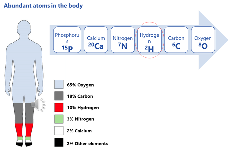
In order for MRI to work, we need to have something to image. Recall that the protons in the body spin, creating a tiny electromagnetic force. Theoretically, we could image ANY proton in the body, however, if they are not in abundance they will give off a very little signal. The more protons of the same element, the more signal will be created. The most abundant atoms in the human body are, in order starting with most abundant are: Oxygen, Carbon, Hydrogen, Nitrogen, Calcium and Phosphorus.
Recall also, that the atom of choice MUST have an odd number of protons. In examining the number of protons for each, we see that Oxygen has 8 – that is an even number, so it cannot be used. Next is Carbon, with 6 protons, so that cannot be used.
Hydrogen only has 1. 1 is an odd number. Note that Nitrogen with 7 and Phosphorus with 15 are also odd numbers, but they are not as abundant in the body. Please remember, that is the atom that has to be abundant, not the number of protons. It just has to be an odd number of protons. Why is hydrogen so abundant?
Consider the fact that the human body is more than 65% water. All tissue has some amount of water in it. Take the fat cell for instance, it is made of 80% water. The water molecule has two hydrogen atoms for every 1 oxygen atom – that’s why it’s H2O, right?
Imagine the inside of the human body is a nightclub. In a nightclub, there is a lot of background noise. In order to obtain a strong signal, the large population within the nightclub has to react, in order to hear them above the background noise.
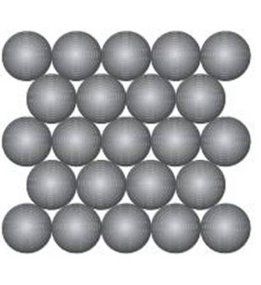
As we have mentioned, the human body is comprised of more than 65% water. Consider the water molecules to be the dancers in the nightclub. Because it is a large population, it will give a strong signal. We will learn more about this later. For now, let’s closely examine a water molecule and a fat molecule.
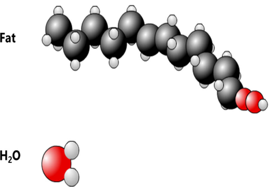
Here we see 2 molecules: Fat and Water. The hydrogen atom, represented by the smaller circles, is present in large quantities in both. Of course, fat and water are not the only molecules in the human body containing hydrogen. As mentioned earlier, Hydrogen is the third most abundant atom in the human body. There is some amount of water and/or fat, in all tissue in the body. There are two hydrogen atoms in every water molecule and there are as many as 12 hydrogen atoms in a molecule of fat, depending on the type of fat. Again, because it is so abundant in the body it will give off a strong signal.
Let’s take a closer look at the hydrogen atom. Hydrogen is considered a simple element. It is composed of 1 proton and 1 electron. The hydrogen atom is considered to be a dipole because of this simple structure. A dipole in rotation, or what we refer to as spinning or precession, is represented by a magnetization vector. The magnetization vector of each hydrogen atom is called the “icroscopic Magnetization Vector”. We will see later that in MRI, we work on the “Macroscopic magnetization vector” – which is the sum of all of the microscopic magnetization vectors.
In other words, each individual hydrogen atom has a magnetization created by the spinning dipole. However, in MRI we need to consider the Sum magnetization of ALL of the spinning dipoles.
Before we go any further in that discussion, we need to understand a little more about the magnetic field. You may recall in grade school or later, playing with magnets in science class. These magnets would have been many millions of times LESS powerful than the magnet used in MRI. However, they all work with the same regardless of the strength. It is all the same physics concepts. This basic idea with magnetization is really the basis of MRI imaging. Let’s learn more about the magnetic field in MRI.
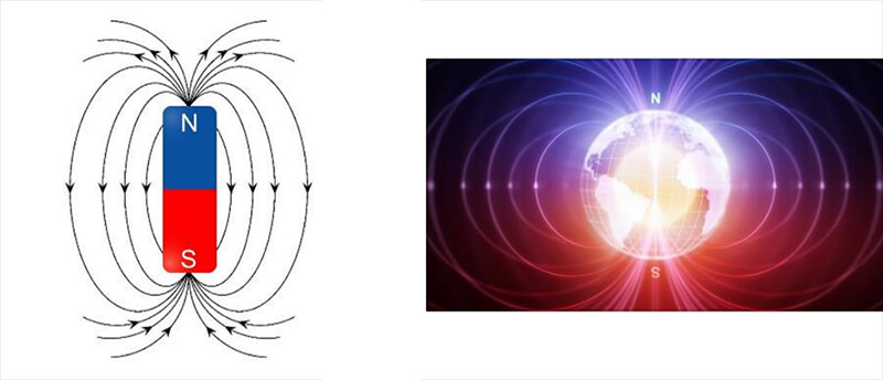
A magnetic field is defined as a region around a magnetic material or a moving electric charge within which the force of magnetism acts. Magnetism is an attraction and repulsion of forces between objects. This magnetism is observed around the earth. The earth is a larger scale example of a spinning object, which is also a dipole (north and south pole). The magnetic field of the earth allows us to use a compass to determine direction. We can also observe a magnetic field around permanent magnets and coils fed by electrical charge.
So, how do we create a magnetic field? If we place a permanent magnet on a surface coated with iron filings we can easily see the field lines on both sides of the magnet. Because of the ferrous properties of the iron filings, they are naturally attracted to the magnet. The Iron fillings with gather around and attach to the magnet within these field lines. Even if they do not all attach directly onto the magnet, they are within the magnetic field.
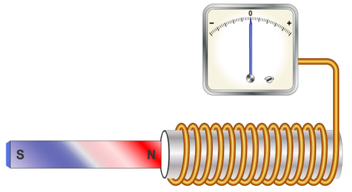
Two early 19th century discoveries ultimately led to the discovery of MRI late in the 20th century. Both of these discoveries are explained on the following slides. The experiment of Ørsted shows that a circulating current induces a magnetic field.
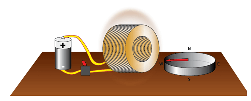
In 1820 after a long series of experiments, Ørsted discovered that a magnetized needle placed near a conductor moved when the wires were connected to a battery. At the time, the notions of electric circuit and current were unknown, but Ørsted suspected a link between electricity and magnetism. This experiment was the inspiration for the invention of coils to generate a magnetic field. If we turn the switch on, electrical current can flow through the coil and create a magnetic field.
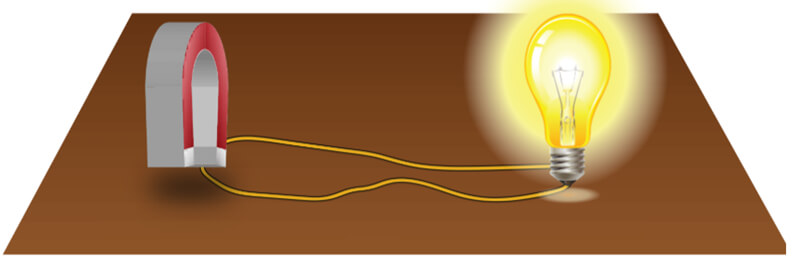
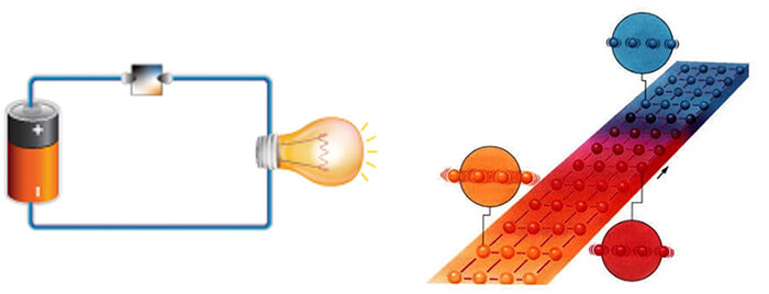
In 1821, following the discovery of the phenomenon of electromagnetism by the Danish chemist Ørsted, Faraday built two machines to produce what he would call an electromagnetic rotation: the continuous circular movement of a magnetic force around a wire is the principle of an electric motor. In this experiment, if we rotate a magnetic field, shown here as a u-shaped magnet, it creates an electric current, to power a light bulb in our example.
This is still the way we generate electricity today. The magnet used is rotated as a result of the power created by the action of water such as with in hydroelectric power plants, with heat in conventional or nuclear power plants, with wind as in windmills or with mechanical effort, dynamo.
Magnetic fields can be of varying strengths. In MRI, even within one magnet, the strength may vary. In MRI, the magnets used must be as homogenous as possible. Homogenous means to be the same. In this case, we want the magnetism to be the same, as closely as possible. If homogeneity is not ensured, the system will operate poorly.
There are three basic classifications of magnets used in MRI. Permanent magnets, resistive magnets and superconductive magnets. Each has its own advantages and disadvantages. Let’s look at each individually.
The permanent magnet used in MRI is based off the science behind magnetized ore, or Magnetite. Magnetite is an ore composed of iron and oxygen that naturally attracts iron and some other metals such as nickel and cobalt. Legend has it that an old shepherd named Magnes found that his boots were attached to a rock by their nails. This happened in northern Italy in a region called Magnesia. The rock took on the name of magnetite from Magnes or Magnesia.
When a needle of magnetite was placed floating on water, it always pointed north: this was the birth of the compass… The alloys most often used today in MRI are ALNICO (aluminum, nickel, iron and cobalt) or ferrites (iron oxide- and cobalt-based ceramics). The bricks, of which ever material is used, are magnetized, and then assembled into the structure of the MRI magnet. They will maintain their magnetization until they are disassembled. Thus the term, Permanent Magnet.
Permanent magnets are limited in magnetic strength, usually having a magnetic field strength of approximately 0.5 T. These limitations led builders to select other methods to obtain intensities higher than 0.5 T.
Permanent magnets are not very strong as far as magnetic field is concerned. In order to be able to produce a high intensity magnetic field, a permanent magnet would have to be of monumental size. This is because each of the magnetized bricks has a given amount of magnetization. It cannot be increased or decreased. The only way to make the magnet more powerful would be to add bricks and make it larger.
The weight of this type of magnet can reach several hundred tons. The prior restriction in terms of size is consistent with a magnet that is very heavy. A permanent magnet that can provide a field of 1 T can easily weigh 300 tons. This evidently imposes severe measures to be taken for the premises housing these machines. Another restriction with a permanent magnet is that they are not very homogenous. As we have seen before, we must have the most homogeneous magnetic field possible in order to obtain a good MRI image.
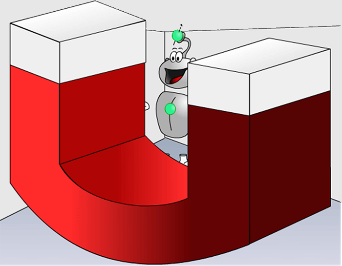
A permanent magnet by default does not readily furnish a homogeneous magnetic field. This is why Hydro seems to have been drawn by a cubist painter. Fortunately, there are methods to improve the homogeneity of the magnetic fields created by permanent magnets.
Again, Permanent magnets are not very powerful. As a result of the restrictions we talked about, a permanent magnet cannot create strong magnetic fields. Builders prefer selecting other methods to obtain magnetic field intensities higher than 0.5 T. This kind of magnet does allow for an open magnetic field and it does not require much consumption of power.
The open style of this magnet is beneficial for claustrophobic patients as they will feel less enclosed in a machine with openings on the sides. They may allow for the patient to turn their head and look out, depending on the examination. They may allow more room for obese patients or allow a family member to sit next to the scanner and hold the patient’s hand. One must be aware, however, that an open MRI may be closer to the face to make up for the open sides.
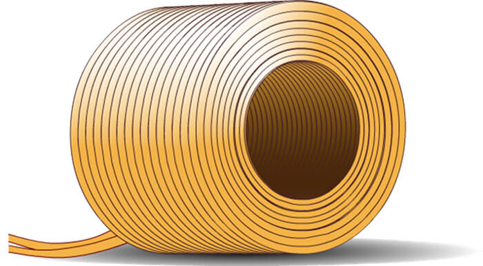
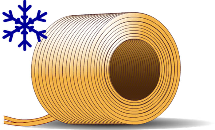
The next type of Magnet used in MRI is the Resistive magnet which is characterized by a copper wire coil.
As we saw when explaining the experiment of Ørsted, a rotating current creates a magnetic field. This is the property used for this type of magnet. A coil created by winding copper wires produces a magnetic field when an electric current flows through it. The direction of the magnetic field will depend on the axis of the tunnel of the coil. The intensity of the magnetic field is proportional to the intensity of current passing through the coil.
Resistive magnets have a homogenous field. One of the advantages of this type of magnet is that it provides magnetic fields of good homogeneity that can be used in MRI. These magnets are used in all MRI machines to generate gradients. Resistive magnet, like permanent magnets, have a weak field. Also, electric consumption by resistive magnets is very high. This is why they are generally not used to create the principal field of a whole-body MRI beyond 0.5 T. This type of magnet is nevertheless used in MRI to create magnetic field gradients.
Resistive magnets are huge energy consumers. This is the major disadvantage of this type of magnet. As we said earlier, the intensity of the magnetic field is proportional to the intensity of current passing through the coil. Unfortunately, its resistivity results in a very low energy yield. This is why this type of magnet is very rarely used in MRI to create an intensity higher than 0.5 T. That brings us to superconductive magnets. This type of magnet is the most common type of magnet in use today in MRI. It is similar to the resistive magnet In that there is a copper wire coil.
This type of magnet uses a coil composed of an alloy and that is immersed in liquid helium. This type of magnet is based on the principle of Ørsted that is used in resistive magnets with the addition of the principle of superconductivity.
Superconductivity was discovered by Kammerlingh Onnes in 1911 when he chilled metals in liquid helium down to a temperature of about 4 degrees Kelvin. He demonstrated the loss of resistivity of a material when it was cooled below a certain point, called the critical temperature. Alloys currently used have a very high critical temperature (140°K), much higher than the temperature of liquid helium. This explains why it is now much less expensive to obtain superconductors. When the magnet is placed in the helium bath, a current is injected in the circuit and then circulates without resistance, providing a constant and intense magnetic field.
The super conductive magnet is nearly homogenous. Homogeneity is the biggest advantage of of the superconductive magnet. They are thus frequently used to generate the principal magnetic field (especially beyond a certain intensity). Superconductive magnets are very powerful and can provide very high intensities. For magnets stronger than 0.5 T, this is the type of magnet used. Superconductive magnets range in energy levels, or magnetization levels. The most common strengths used in medical imaging is 1.5T or 3T, but there are magnets in used today that are as strong as 8T or even 10T.
One of the disadvantages of a superconductive magnet is the large amount of energy needed to keep helium in its liquid state. We explained before that consumption by this type of magnet is very low. It is not null but it comes down to the energy required to keep helium in its liquid state. This is most often done by using a cold head that compresses gaseous helium and thus maintains the cold source.
Resistance is practically zero: the hedges are very low and do not impede the progress of our runner. If we allow the system to warm up, for example by venting off some liquid helium, the temperature increases and along with it resistances of the alloy through which the current passes. The current is blocked and with it the magnetic field it was producing.
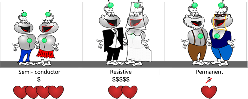
To summarize the different types of magnets, let’s use a metaphor to better understand the differences and similarities. Consider the life of a couple at different stages of life. The superconductive magnet is represented by the couple during the majority of their marriage, the resistive magnet during the early stages of a marriage and the permanent magnet by the older couple nearing retirement.
In the beginning of the marriage, there is palpable passion but that requires input to maintain because of expenses (jewelry, dresses, a house, children, etc…). Thus, even though resistive magnets offer more advantages in use than permanent magnets, they are high energy consumers. Finally, passion in the young couple is at its maximum. This requires some, but not excessive maintenance costs (flowers, a cinema, restaurant…). The electromagnet provides the best advantage/consumption ratio.
In the final stages of marriage, as the couple gets older and their children are grown and no longer in the house, the couple is comfortable with each other, they are committed and just enjoying their lives. Little effort is needed to maintain the commitment, little energy is required, like the permanent magnet.
Now that we have a basic understanding of magnets and magnetic field, we need to look at radiofrequencies and the role they play in the production of an MRI Image.
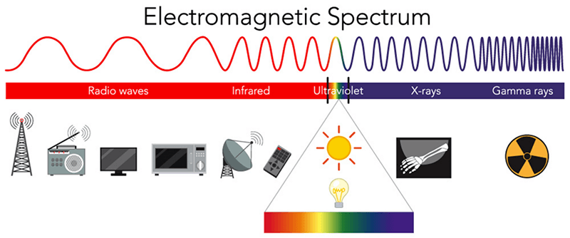
Radiofrequencies are part of the electromagnetic spectrum. They are found on the low energy end of the spectrum, far below ionizing radiation. Recall that energy is related to frequency directly: the higher the frequency, the higher the energy level. The higher the energy level, the higher than likelihood of ionizing the atom. You may here it said that MRI does not use radiation at all. A more truthful statement would be that no IONIZING radiation is used.
When the hydrogen protons are introduced to the magnetic field, the dipoles of the protons will align to the magnetic field. It is the RF energy that is applied to the protons in order to disturb them. The radiofrequency used must be at the same frequency as the frequency of the spinning hydrogen proton. Recall I said earlier, all protons spin at different frequencies at which they spin. We will get into more detail about this later, but for now just know these facts.
As mentioned earlier, we need all three things. The strong magnet, the protons and the RF. If the RF was taken away, the protons would simply stay aligned to the magnetic field. It is the disruption of the protons that will ultimately create the signal measured during an MRI examination.
The last topic to discuss in this introductory module is safety. MRI is a very safe examination under the right conditions. But in the wrong conditions, it can be potentially dangerous. A good understanding of MRI safety is essential.
The second video below made available by the Sahlgrenska University Hospital, Gothenburg in Sweden shows the effect of magnetic attraction on a small oxygen tank. The patient’s head is replaced by a watermelon. We also see the damage caused to material (the coil) that is a very expensive MRI component. The violence of the impact is obvious. Please take a minute to review the video before moving on.
The third video below also made available by the Sahlgrenska University Hospital, Gothenburg in Sweden shows the consequences of using a bed incompatible with MRI that is too close to the machine. The watermelon here represents a nurse between the bed and the machine. Again, take a few minutes to review the video.
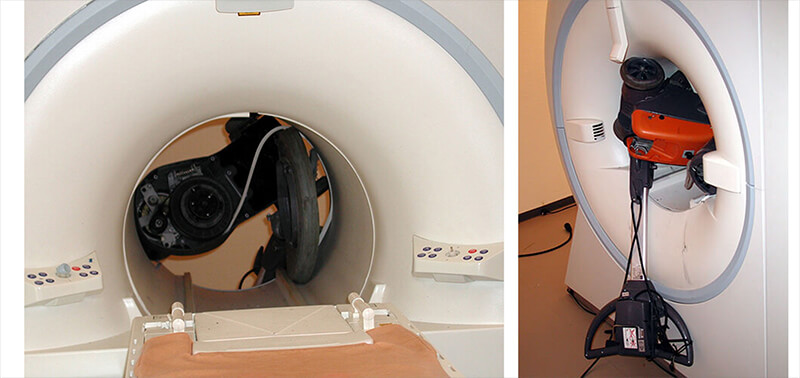
There are many things in a hospital or imaging center which can become dangerous projectiles in the MRI suite. The first two images (check below) show a floor polisher in a 1.5 T MRI room and the last four are a bed in a 3T MRI room. We can imagine the violence of the shock and, compared to the fourth video below, we see the difference in force with a 1.5 T machine. A patient was in the bed at the moment of the shock and fortunately there was only material damage.
This accident is relatively common and must be prevented especially when starting an MRI activity within an institution. At times, Safety rules are not well transmitted and if we add the curiosity of people to explore the machine closely, this increases the risk of accidents. For these reasons, it is essential that all staff who could potentially come into the MRI suite be screened and properly trained about the dangers of a very large, strong magnet.

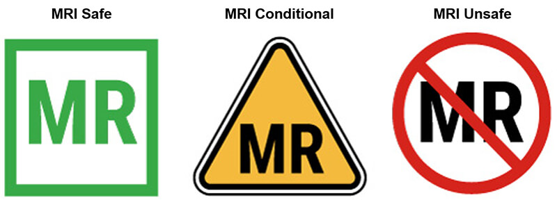
In addition, we have to be concerned about what object are inside the patient or any person entering the MRI suite. There are implants that are permanently placed inside a patient. These items are classified as MRI Safe, MRI Conditional or MRI Unsafe. For this module, we want to talk about the objects which are contraindicated or not compatible. Of course anything ferrous, outside the patient is contraindicated because they have the potential to be projectiles.
Patient related contraindications fall into two categories:
- Absolute contraindication such as a pacemaker, Stimulators, aneurysm clips, and metal fragments in the eye
- Relative contraindications such as pregnancy, obesity, and claustrophobia
Even some absolute contraindications may be scanned on certain MRI units and under very specific conditions.
One of the reasons MRI accidents happen is because workers not familiar with the modality tend to think the MRI is only on when they technologist is working and scanning a patient. This is not true. The “MRI IS ALWAYS ON”. The only time a superconductive magnet loses magnetization is during a quench.
A quench can occur on its own or it can be initiated by the technologist. A quench occurs when the quick exhaust of helium implies a warming of the coil. The coil then becomes resistive, and the current flowing over the field stops.
The Internet site www.mrisafety.com keeps an updated safety-watch on contraindications in particular the compatibility of different types and models of biomedical materials. The below video is taken from a film, used by a manufacturer to make maintenance worker aware of the hazards of MRI Machines.
We see a factory quench, that among other things shows the volume occupied by helium once in the gaseous state. The size of the gas cloud is placed in perspective with the size of the person behind it in the video. An MRI in operation contains about 2000 liters of liquid helium. When in the gaseous state, its volume is about 720 times greater, about 1,440,000 liters of gas.
In this video below we get a better idea of just how much helium is released during a quench. It shows a quench when an MRI machine is replaced. The helium would have been removed from a machine being moved like this, however some helium in the liquid state always remains – it is not possible to remove it all.
When the lift gives out and the magnet is suddenly turned it creates a situation to allow the liquid helium to escape, which does so in a gaseous form. Just as it would during a quench of the magnet. Here, being outside, the gaseous helium can be dispersed better. But imagine inside the MRI room with the door sealed shut. Even with evacuation ducts to release the helium to the outside of the building, the helium would quickly fill the room, reducing oxygen levels and sometimes creating a seal at the door. This video was obtained from an on-line video sharing site.
Helium is a colorless odorless gas which is why it is undetectable by human senses at low concentrations. However, it may compete with or replace oxygen and cause asphyxia. This explains why the oxygen concentration is monitored in real time.
If it decreases below a certain threshold, the examination room must be rapidly cleared of all personnel: this is the sign of an invisible helium leak. The oxygen concentration in the air is insufficient for human breathing.
Sometimes, the pressure created in the room creates a vacuum at the door. MRI rooms always have a window between the control booth and the scan room. It may be necessary to break the glass in the window if the door will not open. IN the United States, it is recommended to keep a non-ferrous hammer or other large object close by for this reason. If you have nothing like that nearby, find something that is MRI safe to break the window, even a desk chair will work.
This concludes the introduction to MRI and related equipment. Let’s summarize what we have covered.
There are 3 requirements to obtain an MRI Image: A strong magnet, an abundant atoms with an odd number of protons, and a radiofrequency which is a non-ionizing form of radiation.
MRI is a very safe medical imaging modality, but under certain conditions there are very serious risks involved. The most important being the magnetic pull is powerful which can be very dangerous around ferrous materials.
There are 3 main types of magnets: Permanent magnets are used for low field intensity MRI systems (less than 1 T), resistive magnets which are generally NOT used to create the main magnetic field and Superconductive magnets, or high-field magnets used in MRI systems over 1 T.
A rotating current generates a magnetic field and vice versa: a rotating magnetic field generates an electric current. In emergency situation, a Quench can be provoked to stop the magnetic field of a superconductor magnet. Now it’s time to take your quiz and issue your certificate. Please proceed to the quiz for module one where you will find additional instructions.
Previously, we learned how magnetization works and how RF energy is used in MRI. We now have to understand the safety-related to magnetization and the attraction of ferrous metals. We will discuss the transfer of energy during RF transmission, as well as dangers presented which can cause RF burns. And we will discuss the difference between MRI safe, MRI conditional and MRI contraindicated affect us at work.
Magnetization
The idea of MRI came from a discovery in 1831! Michael Faraday discovered that when there was a change in magnetism within a coil of wire, a voltage resulted. When the bar magnet moves into the closed-loop, the voltage increases. When the bar magnet is removed the voltage goes down. We refer to the force created as the electromagnetic force.
Of course, Faraday had no idea that at some time in the future, we would use this technology to create electromagnetic engines, OR use the same principles to create images of the internal structures of human anatomy. The MR signal that results during an MRI examination is a small electrical current induced by the receiver coil by the precession of the net magnetization during the MR scan.
But to create this phenomenon, we must create a situation where the voltage and electromagnetic energy increases and decreases. To understand all of this, we must have a full understanding of the safety concerns surrounding these concepts.
Ferrous and Other Properties of Metals
When one thinks of MRI, they cannot help but think about the magnet. After all, one cannot help but notice the warning signs everywhere! Recall the magnet used in MRI is very strong. Magnets attract metals. But that is not the only concern about metals in MRI. Metals have many properties to raise concerns.
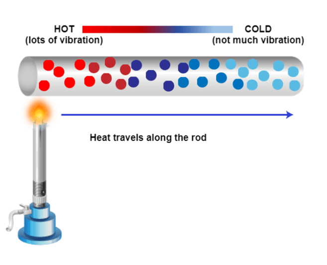
Metals can be conductors of heat and electricity. Previously, we learned about how introducing a magnet into a closed coil can increase voltage. This can be a concern with certain metals in the magnet. The conductors can be dangerous under certain conditions, which we will discuss in a bit.
The next property is that metals are high-density materials. We have briefly discussed the need to have protons in precession to create a signal that can be recorded. High-density materials are not measurable in MRI because the protons are too densely packed. If metal is in the area of interest during an MRI scan, there will be a void on the resulting image or a huge black area of no signal.
Lastly, metals can be ferrous. This means they are magnetic or attracted to the magnet. Ferrous metals are the most dangerous to have near the magnet because the magnet is always on. Let’s look at these a little more closely.

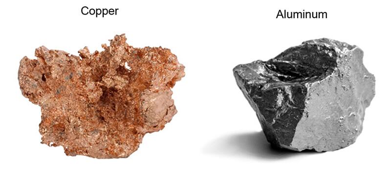
Here we have two examples of conductor metals. Copper and Aluminum. Occasionally these types of metals are used as part of medical implants. Copper may be used in lithium batteries. Devices such as Pacemakers and bladder stimulators may have these lithium batteries. Some of the wires used with pacemakers and stimulators may have copper or other conducting metal alloys as part of the wire. That, combined with the moist tissue inside the body are the perfect combination for transfer of the energy created during a scan.
As mentioned earlier, the biggest problem with high-density metals is the artifact or image degradation that occurs on the resulting image. Most orthopedic devices such as artificial hips, artificial knees, pins, screws, etc are all made of these types of “MRI safe” metals, however, the images are not useful. In addition to the metals not creating a measurable signal, the surrounding signal is often distorted.
Contrary to what many people think, these metals will NOT be pulled out of the body or heat up, the MRI is just not diagnostic. Some piercings or other jewelry may be made of these metals. These types of items are removable for the scan and recommended. If the jewelry is within the coil, and in the area of interest, they will still create artifacts that may affect image quality. Some examples are tungsten, lead, titanium, and gold.
High density:

The most important consideration is ferrous metals. These metals pose the greatest risk to everyone in the MRI suite because of their strong attraction to magnets. Products created of steel or steel products are of greatest concern. Steel is derived from iron ore. Iron ore is used as additives and alloys with many other types of metals.
At times, these types of metals are used to save money or provide additional strength to other types of metal. For this reason, ALL metal should be tested with a FERROUS METAL DETECTOR, not just a metal detector. A metal detector tells us it is metal, a ferrous metal detector tells us if it’s ferrous.
Ferrous:

Transfer of Energy
One of the great principles of physics is that energy cannot be created or destroyed. Thinking back to Faradays Law, we learned that during the process we are creating a current with the varying magnetization. A portion of the energy created will be in the precession and subsequent relaxation and signal that is produced. But not all of the energy becomes signal. Some are heated. Where does this heat get deposited? Usually within the patient.
However, if there is something present that works as a conductor, the heat may be deposited there. We mentioned metals as conductors but other materials may conduct also. If any of these conductors are touching the patient’s skin or internal organs, and RF (radiofrequency) burn may occur.
RF Burns
RF burns may result from the patient’s skin touching the sides of the bore inside the scanner. That connection of the tissue to the inside of the machine allows for direct transfer of heat. Moisture will also be a conductor. Sweat or moisture within the folds of the skin or even a damp diaper may provide just enough moisture to conduct a current and allow for a burn.
Many, but not all, medication patches have liquid within them and are designed to allow that liquid to flow from the patch to the skin, creating a moisture level on the skin as well. Hospital monitoring equipment touching the skin may also create a conducive situation. Oxygen monitors or a pulse-ox, have been known to cause burns, leads from EKG monitors or even IV tubing filled with liquid, IF touching the skin directly, may lead to RF burns. And of course, metals, which we have already discussed.

The dangers of RF burn, while rare, are very serious. Here we see a burn that was caused by a coil touching the patient’s skin. MRI burns are not always visible immediately. The skin may just feel warm to the touch at first. But MRI burns will worsen with time AFTER the scan has ended, and can get progressively worse over time without intervention.
The worst burns result in blistering of the skin, then peeling off the skin and sometimes scaring, similar to the results of getting a sunburn. There have been documented cases where patients require skin grafts after an MRI burn.
The best ways to prevent burns: Make sure there is a minimum of 10mm of padding between the patient’s skin and the inside of the bore. Make sure nothing that can act as a conductor is in direct contact with the patient’s skin. Lastly, make sure moisture is kept to a minimum on the patient’s skin during a scan.

Safe, Conditional and Contraindicated
One thing we have little control over is what is inside the patient. The good news is that most if not all devices used as medical implants today are tested for MRI safety. We can practice good safety with external items, such as checking for magnetic properties, removing removable items, and providing padding between the patient and medical equipment which should not touch the patient’s skin.
For objects inside the body, we need to be more cautious. Operation reports are obtained to get information about the implant, then that can be looked up in a safety manual such as Shellock’s Reference Manual. Some companies may include MRI safety information on their websites. Regardless of where you look, there are three terms to know.
- MRI Safe: the object is safe to enter the MRI suite and maybe scanned under any condition
- MRI Conditional: the object is safe to enter the MRI suite and maybe scanned as long as specific parameters are followed
- MRI Unsafe or MRI Contraindicated: the object is NOT safe to enter the MRI suite and may not be scanned under any conditions
Now that we know what types of things to be concerned about in and around the MRI suite, we will now discuss MRI Zones and who can be in each zone.
Why Zones Are Important
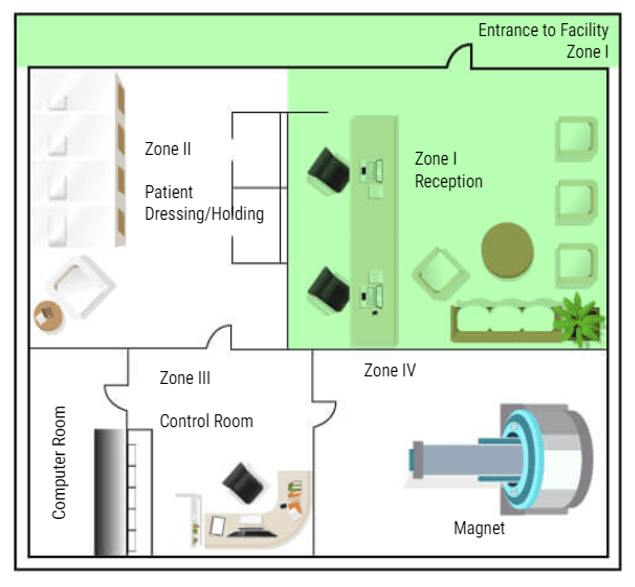
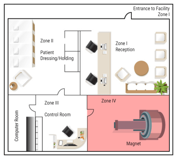
In MRI we divide the work area into four zones. Each zone is very specific about who may enter and under what conditions. All zones must be marked in and around the MRI suite. There must also be a clear definition of where one zone ends and one begins, such as a doorway, chain/rope or another clearly visible sign. The signage should include who is allowed beyond that point. Let’s look at each zone:
Zone 1
Zone 1 is for the general public. Anyone can be in zone one. Some examples are hallways near the MRI area, the main waiting room, or a shared waiting area with other departments. There is NO screening needed to be in Zone One. While in zone one the patient may be asked to complete a screening sheet or be asked some basic safety questions before being moved to zone II.
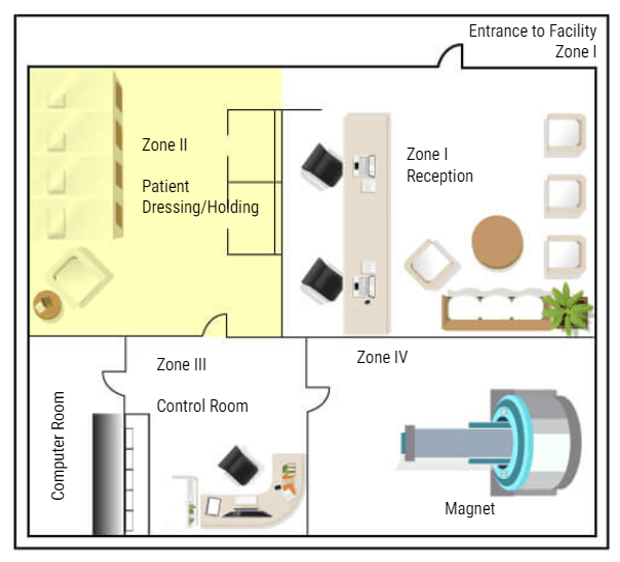
Zone 2
Zone II is where a more thorough screening will take place. The patients will also be prepped for their scans in this area – changing clothes, removing all metal items and placing them in a safe place. Patients are only permitted to enter zone II when accompanied by a healthcare employee. Family members may also be permitted in Zone II accompanied by the healthcare worker without being screened. But this is the anyone not screened or cleared my go in the MRI area. ALL questions should be answered while the patient is in this area. Even if the patient has completed a screening form, they are not permitted beyond this point until they are cleared or accompanied by Trained MRI professionals.
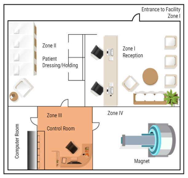
Zone 3
The next zone is Zone three. This is the control area, where the MRI technologist would operate the scanner. Patients should be accompanied by an MRI safety trained individual to enter zone three. People who have not removed loose metals, or who have pacemakers or other unsafe medical devices, should not be permitted in zone III because of the proximity to zone IV. A screened but uncleared person may enter zone III ONLY under strict supervision by trained personnel, such as a patient who just wants to look at the MRI scanner to decide if they will be able to tolerate the exam.
Zone 4
The final zone is zone IV, the MRI scan room. ONLY CLEARED patients are permitted to enter Zone IV, accompanied by trained MRI personnel. The final step of clearance, while in zone III, should be to check the patient one last time for loose metals, other electronic devices and a last check of the critical screening questions. ACR suggests asking these questions a minimum of three times. Once At scheduling, once at screening and once at clearance. As an additional safety measure, many facilities build a metal detector into the doorway between Zone 3 and Zone 4. But there are hand-held devices that work well too and they are less expensive. Once the patient is cleared they can be taken into the MRI room and scanned.
Next, we will talk about MRI screening. I have mentioned several times the need for MRI screening. While we will be focusing our attention on the patients, ANYONE who will enter ZONE TWO or higher needs to be screened. Any employee who works in or around MRI needs to be screened. Local law enforcement, fire and EMT personnel should all be screened if there is a likelihood they will be responding to your facility. Housekeeping and maintenance workers must be screened – these individuals should also be trained in magnet safety.
MRI screening is probably one of the most important tasks related to patient care in the MRI environment. Let’s look at the process a little closer.
Screening Process
Many individuals are involved in the MRI screening process. The ordering physician’s office will call to schedule the MRI and be asked several questions: does the patient have a pacemaker, have they had any brain ear or eye surgery, are they diabetic, how old are they, do they have any surgical implants.
These are questions need to be asked BEFORE the exam can be scheduled. This “pre-screening” as it is called, is done so that the MRI safety officer can be alerted that more information is needed – such as Operation reports, or lab work, or serial numbers from implants. This process allows the answers to be obtained before the patient gets there so that an exam doesn’t need to be rescheduled or delayed. Once the Pre-screening is complete the patient will be scheduled for an examination.
Typical Screening Form
When the scheduled date arrives, the patient arrives for their MRI and is given a more detailed screening form. Patients are usually required to sign these screening forms to attest to the correctness of the information. The screening form will repeat the questions done at pre-screening, but now this is a signed copy of those responses. Some questions on the screening form give information about other tests that have been done and information to help with the diagnosis of this exam.
The technologist then checks this screening form to make sure there is nothing that requires additional information is needed for clarity. If all goes well, everything had been taken care of at Pre-screening and the patient is ready to move on for the scan. Take a few moments to look at this example of a screening form and the types of questions that are asked.

This is the back of a typical screening form. Notice how many times and how many different ways some of the questions are asked. This is done to provide a thorough screening and to NOT have any issues with miscommunication or misunderstanding.
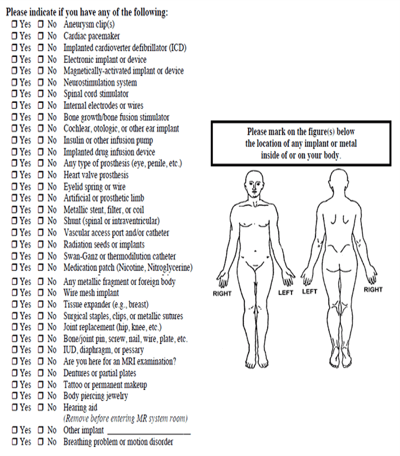
As an example, a patient might have a defibrillator in place, rather than the usual pacemaker/defibrillator. If the screening form was to only ask about pacemakers, a patient may think their defibrillator is ok. Some patients may feel that if something has been inside them for 20 years it is not relevant. And a patient with a bladder stimulator that is no longer functional may not find it important to reveal that it is in place because it no longer works.
A best safety practice would be to follow-up at the end by asking if the patient they have ever had any medical devices implanted in their body.
Who Needs To be Screened
So to summarize this very important section let’s review a little bit:
Let’s test our knowledge. Who needs to be screened?
- All patients who enter zone 2
- All persons who will be in or near zone 3
- All persons who MAY be able to access zone 4
- All employees/staff/students/doctors with a likelihood of working near the MRI suite
- Local Fire and EMS workers
- All vendors who may be working in or around the MRI suite
Again, the general rule is: anyone who may be required to go past zone II should be screened.
MRI contrast is used in about 1 in 3 MRI exams. MRI contrast, like other contrast, provide additional information and clarity in the images. It allows us to see information about organs and structures that may not be visible without contrast – and provides differentiation between tissues. Contrast aids in the diagnosis of certain types of pathologies and conditions and allows us to see vascular structures better. Not ALL exams require the use of contrast, but many do. Gadolinium is used to increase the T1 relation of tissue and is the most common contrast used in MRI. We will learn more about Gadolinium on the following slides.

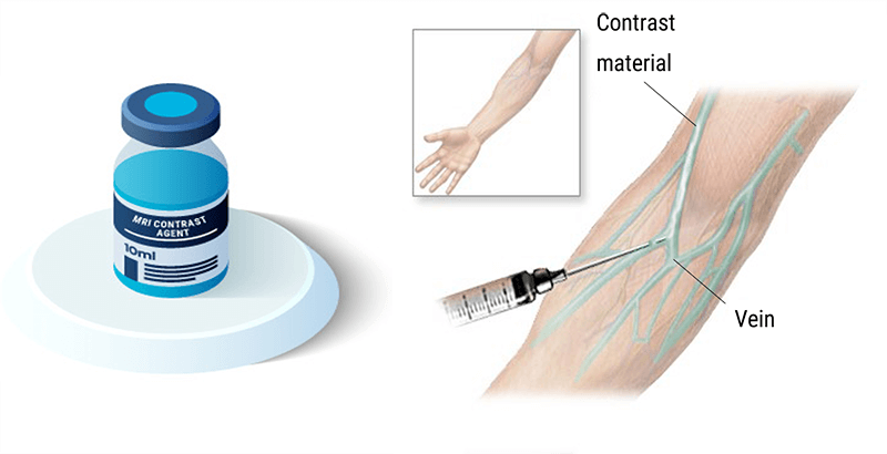
Intravenous Contrasts
The contrast used in MRI is made of Gadolinium. Gadolinium is a metal of the Lanthadines chemical series on the periodic table of elements. The Lanthanide series consists of the transition metals located between the elements of atomic numbers 57 (La) to 71 (Lu) all included. They are also known as rare earth.
Gadolinium has 64 electrons. The size of a gadolinium ion Gd3+ competes with calcium and thus can block the reticuloendothelial system. It competes with calcium at the levels of myocardial contraction, coagulation, calcium-dependent enzymes, mitochondrial respiration, and neurotransmission. For this reason, Gadolinium is the particularly toxic element in its free state. This is why we use it as gadolinium, chelate bound to a linear or cyclic molecule.
Other Contrast Agents
On this slide, we find a non-exhaustive list of various contrast agents that can be used in MRI. We also note that certain contrast agents used are completely natural, and they are not all administered intravenously. Examples of natural contrasts are:
- Water, which is given orally
- Air which is given orally
- Blueberry Or pineapple juice which is given orally
Some examples of artificial contrast are:
- Telescan
- Lumirem
- Methylcellulose
- Vaseline or ultrasound gel
Oral Contrasts
As you can tell from this list, each has different applications and can be used for various reasons. But all serve the same basic purpose. To provide some type of contrast to the scan. Contrast agents can be classified in various ways. Here are some examples of oral contrasts.
Biphasic contrast agents lengthen both T1 and T2 values, resulting in decreased intraluminal signal on T1 weighted images and increased signal on T2-weighted images. Biphasic contrast agents are all water-based, appearing dark on T1-weighted and bright on T2-weighted images. Although in large quantities pure water provides good distention of the stomach and duodenum, it is reabsorbed rapidly in the jejunum making it an inadequate contrast agent for most small bowel imaging.
Positive contrast agents shorten T1 relaxation times and increase the intraluminal signal on T1-weighted images. This is usually accomplished using low concentrations of ferric, manganese, or gadolinium ions. In the 1990’s several of these agents were commercially available, including an enteral formulation of Magnevist® (Gd-DTPA) and LumenHance® (MnCl2). Neither agent is still in production today.
Negative contrast agents shorten T2 relaxation times and decrease the intraluminal signal on T2-weighted images. Negative contrast agents are designed to make the intraluminal contents dark, especially on T2-weighted images. This can be done by filling the bowel with diamagnetic materials (barium, kaolin) or relatively high concentrations of paramagnetic ions (where very short T2 values dominate the effects of short T1s).

Osmolality
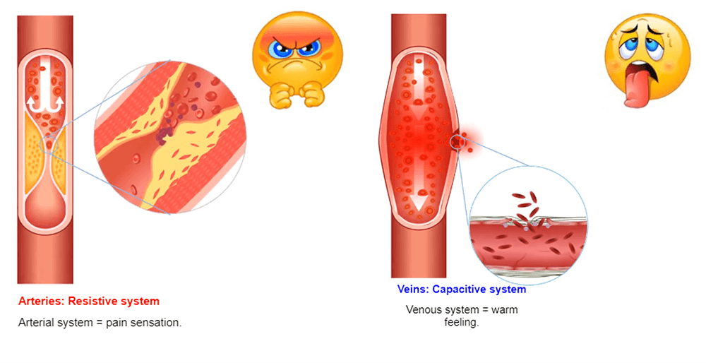
Osmolality refers to the number of particles present in a solution. Blood has an osmolality of 275-295 mosm/kg. Any solution with a higher osmolality than blood is considered hyperosmolar. Gadolinium has an osmolality of 630-1970 mosm/kg. The injection of a hyperosmolar product provokes a call for water from the interstitial to the interior of the vessel: this provokes hypervolume expansion.
The venous system is a capacitive system and it dilates easily causing a heat sensation. The arterial system is a resistive system, the vessel does not dilate easily, which causes a painful feeling.
In MRI, the amount of a substance given to the patient is very low and most of the time, the patients do not feel anything. But, it is always safe to use contrast with the lowest osmolality possible. The information about the contrast used in your facility can be found on the package insert with the contrast.
Effects on the Contrast
The presence of gadolinium will cause an acceleration of T1 relaxation time. In higher concentrations, it will also disrupt the local magnetic field to accelerate the T2 relaxation time. The acceleration of the T1 effect increases the tissue signal which captures the gadolinium in the T1-weighted sequences.
In high concentration, the acceleration of the T2 effect decreases the signal of the tissues which capture gadolinium in the T2-weighted sequences. We also look at the effect on perfusion sequences where we observe the signal drop caused by the magnetic susceptibility provoked by the first strong flow of gadolinium.
Examples of Examinations with Injection
Contrast agents do not cross the healthy blood-brain barrier and are usually eliminated through the urinary tract. In the below examples, we find some demonstrations of the appearance of gadolinium on different structures.
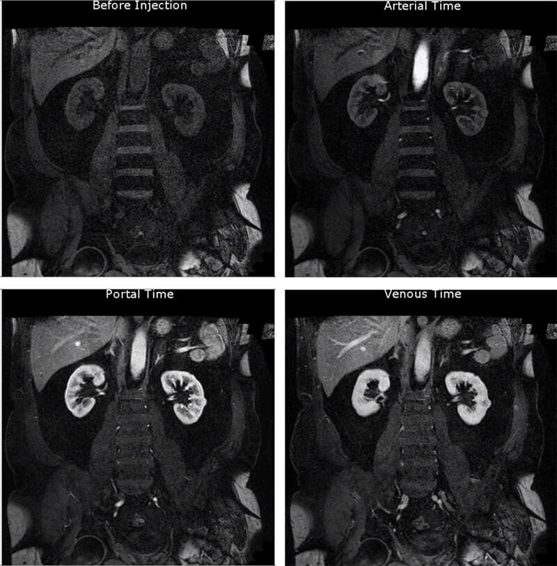
This image is a multiphase abdominal scan. An abdominal acquisition before injection, during the arterial phase, portal phase, and venous phase. We can also observe the vascular lesion of the left kidney.
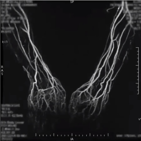
This second image is a 4D sequence of an upper extremity MRA. A 4D-sequence, which is a 3D-sequence with a fast time resolution. The volume is refreshed very quickly.
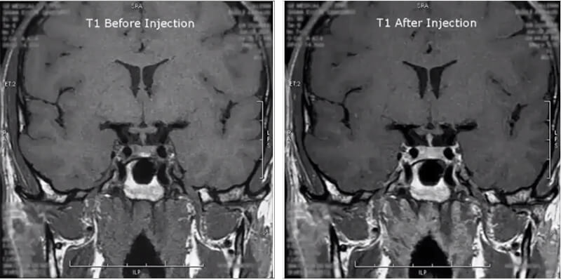
Next is a pituitary study. This image is a coronal T1 of the pituitary gland before and after injection. Notice how the contrast makes the pituitary gland highlight.
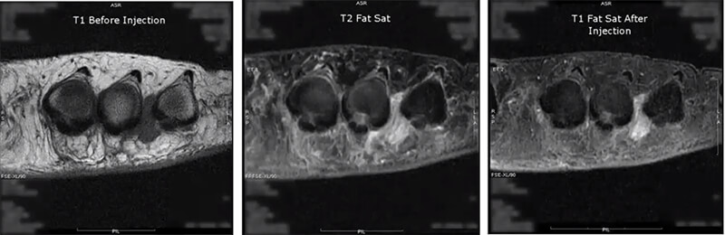
On the fourth image, we are evaluating Morton’s neuroma in T1 and we see that darkened area between two of the toes. Next, we run a T2 fat sat, which suppresses the fat and allows us to see true pathology. Then we run the post-contrast as a T1 injected fat sat. Again suppressing the fat, but notice the contrast enhancement of the lesion now compared to the first T1.
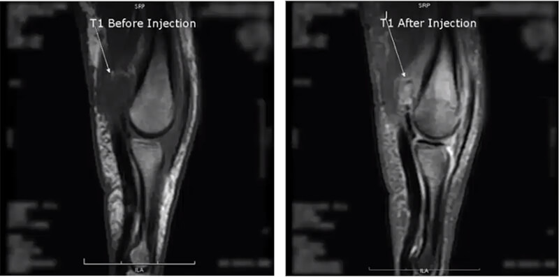
The last image is a finger in the sagittal plane. On the T1 before the injection, we see a dark area, mostly likely pathological fluid, and after the contrast injection again run as a fatsat which is usually the case with extremity images post-contrast, we now see there is pathology hidden within the fluid. This is some form of a lesion which may not have been noticed had contrast not been used.
Agents with T2 Effects
One thing to keep in mind is the blood-brain barrier. In contrast, to highlight something in the brain, there must be a breakdown of the blood-brain barrier. In this video, you can see an area of the brain with decreased blood flow causing an area of fluid to build up. This set of images is taken as a Cine, which means all of the images are taken at the same location over a period of time, to watch how the brain is perfused with the blood, or in this case the contrast. Notice how the area is very dark then it becomes less dark, until finally, the entire brain is all the same shade of gray, except a very small lesion in the middle. This gives you a good perspective of how the contrast continues to change the appearance and weighting of the brain tissue as time passes.
When discussing contrast agents, one must have a full appreciation of the benefits, which we have already discussed, but also the risks. The biggest risk of Gadolinium-based contrast agents is NSF or Nephrogenic systemic fibrosis. Which we will discuss in a few minutes. At present, the only measure that can predict a possible outcome of NSF is the renal function. This involves a simple blood test, which can be done in a doctor’s office or clinic, just a few minutes to a few days before the MRI. We look at the patient’s Creatinine and GFR.
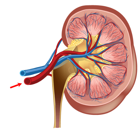
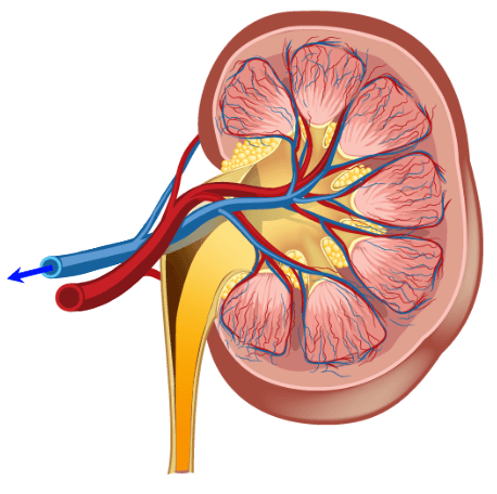
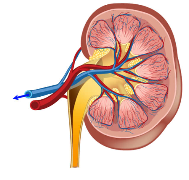
Kidney Function
Kidney function is important to measure when injecting Gadolinium (and some other IV contrasts). It is imperative that the kidneys be working well enough to take the contrast agents out of the bloodstream quickly, usually within 24 hour period. When Gadolinium stays in the bloodstream too long, it will deposit in the tissue and may lead to a condition called NSF, which we will discuss later on.
The kidney function is measured with a simple blood test. The BUN or Blood Urea Nitrogen is measured This will tell how well hydrated the kidneys are. A normal range for BUN is 17-25. The next number is creatinine. The creatine tells us how well the kidney function or how efficiently they are removing excess creatine from the blood. A normal creatinine level is 0.7-1.6.
Always be sure to check the serum creatinine, not the urine creatinine which is expected to be much higher. Lastly, we evaluate the GFR or eGFR because it is estimated. The GFR is the Glomerular Filtration Rate. This number is considered to be more accurate than just a Creatinine because it takes other factors such as age, sex, and ethnicity into consideration. A normal GFR would be anything over 60. On a young healthy adult, it is around 100. Usually, about 60, a result is given>60. One would be concerned about injecting Gadolinium in a patient with a GFR less than 60, and usually, no injection occurs if it is below 30.
NSF
NSF or Nephrogenic Systemic Fibrosis is a condition caused by the deposition of gadolinium in the tissues of the skin because it was not removed from the bloodstream. The deposition of the gadolinium results in a fibrotic response where the tissue will thicken and become fibrous. When joints are involved, the joints will contract. The disease can be fatal because the tissue of the heart, lungs, and liver may become involved as well. While rare, it is a very important side effect to gadolinium which much be understood and appreciated.

Special Considerations
It is difficult to say who should have their renal function evaluated. Every facility will have its own protocol. General considerations are to evaluate diabetic patients because they are at higher risk for renal failure. Additionally, any patient identified as having a history of chronic renal impairment OR patients with any history of acute renal impairment. Elderly patients and those with a history of another organ failure, especially heart failure, are at greater risk of renal impairment. Again, renal impairment means that the contrast will not be removed or filtered from the blood quickly enough to avoid more serious issues, such as NSF.
Patient assessment is a very important component of patient care. There are many ways to assess a patient. Subjective and objective assessment involves asking the subject (the patient) and observing the patient (objective). Some examples would be, the patient comes to us for an MRI and says “I have been feeling dizzy”. This is subjective information, information from the subject.
However, the technologist might notice that the patient has swelling around the ankle, this is objective. Or something that the technologist has observed. In addition to this, we can use vital signs to assess the patient’s condition. In this section, we will review vital signs and also discuss how the MRI equipment may affect the vital signs or the equipment used to measure the vital signs.
Review Normal Vital Signs
There are Four VITAL signs. Vital signs are the “signs of life”. They are blood pressure, pulse (heart rate), temperature and respiration. We have here the normal ranges of the four vital signs. The listed values are for a healthy adult.
Blood pressure is taken with a device called a sphygmomanometer and a stethoscope. The blood pressure gives a number for the heart during contraction, Systolic, or the top number; and the heart at rest – Diastolic or the bottom number. High systolic and diastolic pressures indicate hypertension (high blood pressure) while low systolic pressure is seen it is an indication of shock.
Normal blood pressure is 120/80 in an adult patient. The pulse is taken by feeling with your fingers or with a stethoscope. Common pulse points used to count the pulse rate include the wrist, the neck or the groin. If the pulse is not strong, a stethoscope may be needed and is often used to take a pulse on the chest.
A weak, thready pulse, can be an indication of shock. The normal pulse rate for an adult patient is 60-100 beats per minute. A thermometer tells us what the patient’s internal temperature is. A fever, or elevated temperature, may indicate fever. A low temperature will indicate shock. The temperature can be taken orally, under the armpit, or rectally. The normal temperature for an adult, taken orally, is 98.6 +/- 1 degree. Taken under the arm, we expect the temperature to be lower, and rectally should be a bit higher.
Respirations are often done by simply watching the rise and fall of the chest. Occasionally, when respirations are very hard to see, a stethoscope will be used. Normal respiration in an adult is 12-20 breaths per minute. It is important, in any medical modality, that we know the normal rates associated with these vital signs. They are often our first indication that something is not quite right.
MR and RF Effects on Vitals
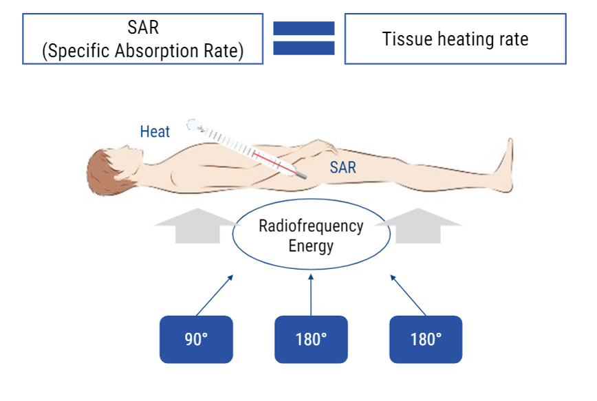
MRI and Radiofrequencies can have some biological effects. One that we talked about briefly is the transfer of energy. This occurs in the form of heat. One of the numbers we watch during an MRI exam is the SAR level or specific absorption rate. The rate at which the body is absorbing that heat. If the body absorbs heat, the temperature of the body will rise. SAR is given in watts per kilogram. A SAR level of 4 is considered the uppermost limit during an MRI scan. We can adjust parameters to help keep SAR levels low.
Other than that, the only other effect on the vital signs it the effect on the monitoring equipment itself. Because of the electromagnetic nature of electronic monitoring devices, the RF energy, and the magnetization, may cause improper readings with the equipment. For this reason, special MRI safe equipment is recommended when the patient must enter the MRI suite and continue to be monitored.
Special Consideration
Some very important things to keep in mind. The equipment used to take vital signs may NOT be compatible with the MRI unit. For this reason, if a patient needs medical attention, it is always best to remove him/her from the MRI room (zone 4) so that they may be safely evaluated. Stethoscopes, oxygen tanks, heart monitors are usually magnetic. Additionally, when patients are hooked up to gating equipment that measures the pulse, respiration or cardiac cycle, be sure to NEVER rely on the reading from this equipment to diagnose a pulse, respiration rate or cardiac cycle. When the RF is applied during scanning, that electromagnetic frequency will cause interference in the electromagnetic waves used to measure either the pulse, respiration or cardiac cycle. You will likely see a warning of this on the equipment.
- There are 3 requirements to obtain an MRI Image: A strong magnet, an abundant atoms with an odd number of protons, and a radiofrequency which is a non-ionizing form of radiation
- MRI is a very safe medical imaging modality, but under certain conditions there are very serious risks involved. The most important being the magnetic pull is powerful which can be very dangerous around ferrous materials
- There are 3 main types of magnets: Permanent magnets are used for low field intensity MRI systems (less than 1 T), resistive magnets which are generally NOT used to create the main magnetic field and Superconductive magnets, or high-field magnets used in MRI systems over 1 T
- A rotating current generates a magnetic field and vice versa: a rotating magnetic field generates an electric current
- In emergency situation, a Quench can be provoked to stop the magnetic field of a superconductor magnet
- Metals have many properties. Of concern in MRI:
- Ferrous
- Conductor
- Dense
- Energy can be transferred to the patient during the MRI in the form of burns
- Implants and devices may be MRI safe, MRI conditional, MRI unsafe
- There are Four Zones in MRI
- Screening procedures and process
- Renal function
- Vital Signs
- MRI gating
- Cardiac
- Respiratory
- Pulse
- Contrast Agents
- Gadolinium – toxic in its free state
- Water
- Air
- Juice
Post-Test & CE Certificate:
Add to CartPrice: $10.00
| ✔ | Approved by the ASRT (American Society of Radiologic Technologists) for 2.5 Category A CE Credits |
| ✔ | License duration: 6 months from purchase date |
| ✔ | Meets the CE requirements of the following states: California, Texas, Florida, Kentucky, Massachusetts, and New Mexico |
| ✔ | Accepted by the American Registry of Magnetic Resonance Imaging Technologists (ARMRIT) |
| ✔ | Meets the ARRT® CE reporting requirements |
As per the ARRT regulations, you have up to 3 attempts to pass the Post-Test with a minimum score of 75%.
Upon the successful completion of the Post-Test (score 75% or more), you will need to fill up a 1 min survey and then you will be able to issue your CE Certificate immediately.
CQR Credits Distribution
| Discipline | Major content category & subcategories | CE Credits provided |
| MRI-2016 | Patient Care | |
| Patient Interactions and Management | 0.50 | |
| MRI-2020 | Patient Care | |
| Patient Interactions and Management | 0.50 | |
| RA-2017 | Patient Care | |
| Pharmacology and Anesthetics Guidelines | 0.50 | |
| RA-2018 | Patient Care | |
| Pharmacology | 0.50 | |
| MRI-2016 | Safety | |
| MRI Screening and Safety | 0.75 | |
| MRI-2020 | Safety | |
| MRI Screening and Safety | 0.75 | |
| RA-2018 | Safety | |
| Patient Safety, Radiation Protection, and Equipment Operation | 0.75 | |
| MRI-2016 | Image Production | |
| Physcial Principles of Image Formation | 1.25 | |
| MRI-2020 | Image Production | |
| Physcial Principles of Image Formation | 1.25 |
Refund Policy: Non-Refundable
